


FX Series Programmable Controlers Applied Instructions 5
5-106
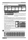
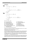
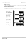
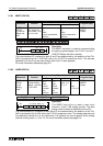
Effective use of the input filter
α
S
3
+2
To prevent the PID instruction from reactin
g
immediatel
y
and wildl
y
to an
y
errors on the
Current Value, there is a filterin
g
mechanism which allows the PID instruction to observe and
account for an
y
si
g
nificant fluctuations over three samples.
The quantitative effect of the input filter is to calculate a filtered Input Value to the PID
instruction taken from a defined percenta
g
e of the Current Value and the previous two filtered
Input Values.
This t
y
pe of filterin
g
is often called first-order la
g
filter. It is particularl
y
useful for removin
g
the
effects of hi
g
h frequenc
y
noise which ma
y
appear on input si
g
nals received from sensors.
The
g
reater the filter percenta
g
e is set the lon
g
er the la
g
time. When the input filter is set to
zero, this effectivel
y
removes all filterin
g
and allows the Current Value to be used directl
y
as
the Input Value.
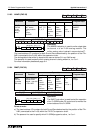
Initial values for PID loops
The PID instruction has man
y
parameters which can be set and confi
g
ured to the user’s
needs. The difficult
y
is to find a
g
ood point from which to start the fine tunin
g
of the PID loop to
the s
y
stem requirements. The followin
g
su
gg
estions will not be ideal for all situations and
applications but will at least
g
ive users of the PID instruction a reasonable points from which to
start.
A value should be
g
iven to all the variables listed below before turnin
g
the PID instruction ON.
Values should be chosen so that the Output Manipulated Value does not exceed ± 32767.
Recommended initial settin
g
s:
T
S
= Should be equal to the total pro
g
ram scan time or a multiple of that scan time, i.e. 2 times,
5 times, etc.
α
= 50%
K
P
= This should be ad
j
usted to a value dependent upon the maximum corrective action
to reach the set point - values should be experimented with from an arbitrar
y
75%
T
I
= This should ideall
y
be 4 to 10 times
g
reater than the
T
D
time
K
D
= 50%
T
D
= This is set dependent upon the total s
y
stem response, i.e. not onl
y
how fast the
pro
g
rammable controller reacts but also an
y
valves, pumps or motors.
For a fast s
y
stem reaction T
D
will be set to a quick or small time, this should however
never be
less than
T
S
. A slower reactin
g
system will require the
T
D
duration to be lon
g
er. A
be
g
innin
g
value can be
T
D
twice the value of T
S
.
Care should be taken when ad
j
ustin
g
PID variables to ensure the safet
y
of the operator and
avoid dama
g
e to the equipment.
With ALL PID values there is a degree of experimentation required to tune the PID loop
to the exact local conditions. A sensible approach to this is to adjust one parameter at a
time by fixed percentages, i.e. say increasing (or decreasing) the K
P
value in steps of
10%. Selecting PID parameters without due consideration will result in a badly
configured system which does not perform as required and will cause the user to
become frustrated. Please remember the PID process is a purely mathematical
calculation and as such has no regard for the ‘quality’ of the variable data supplied by
the user/system - the PID will always process its PID mathematical function with the
data available.
On FX
2N
MPUs pre-tunin
g
feature is available that can quickl
y
provide initial values for the
PID process. Refer to pa
g
e 10-28 for more details.