106 PARAGON II USER GUIDE
Guidelines for Multiple Base Configuration
A multiple base configuration could be two-tier or three-tier configuration. It is composed of
more than one Paragon Main Unit, serving as Base Units, and second-tier or even third-tier
devices.
Initialization
− After all devices have been connected, power on the devices from UPPER tier to lower
tier. For example, power on the second-tier device(s) first and then the Base Units in a
two-tier configuration.
− After initialization, each tier device has an updated database.
Guidelines for changing connections of tier devices:
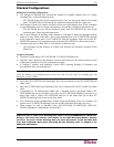
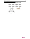
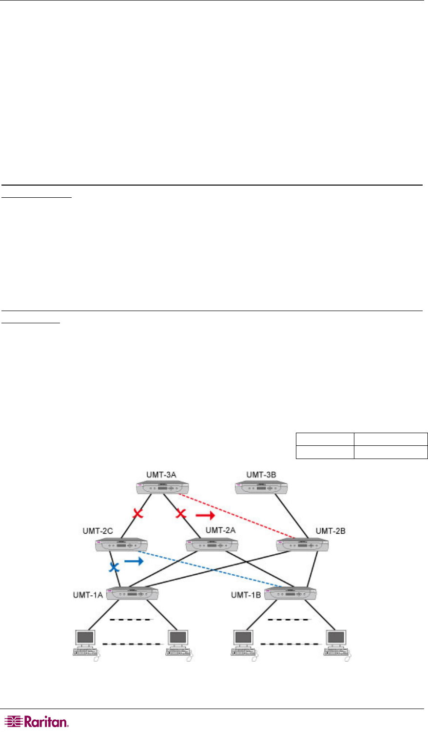
Example A: Relocating a third-tier device with multiple second-tier connections (refer to red line
in the diagram):
1. Disconnect some or all of the user ports on an third-tier unit (UMT-3A) that connect to the
channel ports of second-tier units (UMT-2A and UMT-2C) and re-connect the user ports to
the channel ports of another second-tier unit (UMT-2B).
2. Recycle the power of all impacted devices. This is recommended to build a clean database for
the Paragon switches. Sequence of recycling power is from the HIGHEST tier (third tier) to
the Base Unit. In our example: UMT-3A → UMT-2A → UMT-2B → UMT-2C → UMT- 1A → UMT-
1B.
Example B: Relocating a second-tier device with multiple base connections (refer to blue line in
the diagram):
1. Disconnect some or all of the user ports on a tier unit (UMT-2C) that connect to the channel
ports of a Base Unit (UMT-1A) and re-connect those user ports to another Base Unit (UMT-
1B).
2. Recycle the power of impacted devices. This is recommended to build a clean database for
the Paragon switches. Sequence of recycling power is from the HIGHEST tier (second tier) to
the Base Unit. In our example: UMT-2C → UMT-1A → UMT-1B.
3. The operation is the same for devices that are not Paragon switches.
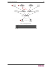
Red color
Example A
Blue color
Example B
Figure 85 Multiple Base Configuration


