


FIGURES v
Figure 52 Sample Messages for Multiple Video Output Results ............................................................... 58
Figure 53 Multiple Video Message on the FOLLOWER User Stations ..................................................... 59
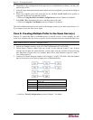
Figure 54 Connection Pattern for Card Reader Functionality..................................................................... 61
Figure 55 P2-EUST/C (Front Side) ............................................................................................................ 62
Figure 56 Login Screen.............................................................................................................................. 63
Figure 57 Administration Menu .................................................................................................................. 65
Figure 58 System Configuration Menu for P2-EUST ................................................................................. 66
Figure 59 Illustration of Forced Video ........................................................................................................69
Figure 60 Forced Video Switch Message ..................................................................................................69
Figure 61 Successful Forced Video Message........................................................................................... 70
Figure 62 Message on the Forced Video User Station .............................................................................. 70
Figure 63 Logout Prompt on the User Station Receiving Forced Video..................................................... 70
Figure 64 Left Panel of the User Configuration Menu................................................................................ 72
Figure 65 Right Panel of the User Configuration Menu.............................................................................. 73
Figure 66 Left Panel of the Channel Configuration Menu .......................................................................... 74
Figure 67 Right Panel of the Channel Configuration Menu........................................................................ 75
Figure 68 Selection Menu .......................................................................................................................... 76
Figure 69 Selection Menu with RGB Skew Delay Active ........................................................................... 76
Figure 70 User Station Profile Screen........................................................................................................ 77
Figure 71 System Reboot .......................................................................................................................... 81
Figure 72 System/Device Reset Screen .................................................................................................... 82
Figure 73 Data Update Message ............................................................................................................... 82
Figure 74 Network Settings Menu.............................................................................................................. 83
Figure 75 Connecting P2ZCIMs as Tiers to Paragon II.............................................................................. 90
Figure 76 Resizing the P2ZCIM Chain....................................................................................................... 92
Figure 77 Refreshing the P2ZCIM Chain ................................................................................................... 93
Figure 78 Connecting Z-CIMs as Tiers ......................................................................................................94
Figure 79 User Profile Menu ......................................................................................................................97
Figure 80 Refresh IBM BladeCenter Servers.............................................................................................99
Figure 81 IBM Blade Server Status After Refreshing............................................................................... 100
Figure 82 Renaming the Channel of IBM BladeCenter Chassis .............................................................. 100
Figure 83 Renaming the IBM Blade Server’s Channel............................................................................. 101
Figure 84 Single Base Configuration ....................................................................................................... 105
Figure 85 Multiple Base Configuration..................................................................................................... 106
Figure 86 Stacking - Single Base Configuration with P2-UMT1664M and P2-UMT1664S ...................... 108
Figure 87 Stacking - Single Base Configuration with P2-UMT832M and P2-UMT832S .......................... 108
Figure 88 Stacking - Single Base Configuration with P2-UMT1664M and P2-UMT1664S ...................... 109
Figure 89 Stacking - Single Base Configuration with P2-UMT832M and P2-UMT832S .......................... 110
Figure 90 ILLEGAL Stacking - Single Base Configuration with P2-UMT1664M and P2-UMT832S......... 110
Figure 91 ILLEGAL Stacking - Single Base Configuration with P2-UMT1664M and P2-UMT1664S....... 111
Figure 92 ILLEGAL Stacking - Single Base Configuration with P2-UMT1664M and P2-UMT832S......... 111
Figure 93 ILLEGAL Stacking - Single Base Configuration with P2-UMT1664M and two P2-UMT1664S 111
Figure 94 Triangle Configuration.............................................................................................................. 112
Figure 95 Single Diamond Configuration ................................................................................................. 113
Figure 96 Double Diamond Configuration................................................................................................ 113
Figure 97 Redundant Configuration ......................................................................................................... 114
Figure 98 Recommended Redundant Configuration Connection Scheme............................................... 115
Figure 99 Illegal Loop-Back Configuration ............................................................................................... 115
Figure 100 Main Unit -- Boot Loader Successfully Upgraded ..................................................................120
Figure 101 Boot Loader Mode of the Main Unit ....................................................................................... 120
Figure 102 Boot Loader Mode of the Stacking Unit ................................................................................. 122
Figure 103 Cat5 Cable Diagram .............................................................................................................. 127
Figure 104 “Direct Mode” Connection Pattern.......................................................................................... 129