CHAPTER 3: OPERATION – USER FUNCTIONS 61
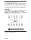
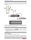
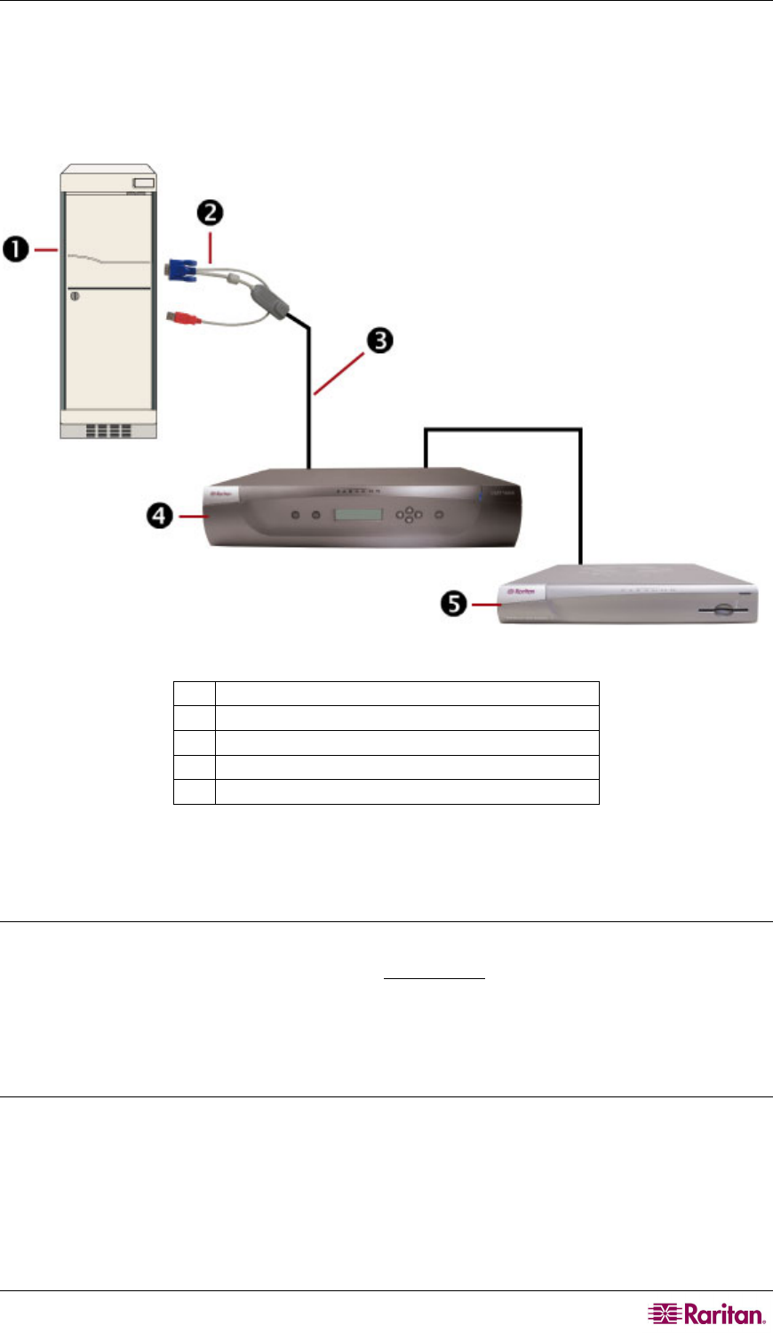
The connection pattern in the chosen path will look like the figure below. Note that if the path
runs through the second- or even third-tier Paragon switches, the firmware version of these upper
tiers must also be 4.3 or above. Otherwise, the card reader function in the path will not be enabled.
For information on connecting user stations, CIMs, servers and Paragon switches, see Basic
Installation in
Chapter 2.
Figure 54 Connection Pattern for Card Reader Functionality
1
Server
2
P2CIM-AUSB-C
3
Cat5 cable
4
Paragon II switch (firmware version 4.3 or above)
5
P2-EUST/C
Warning!! The maximum cable length between the reader-enabled CIM and the Paragon switch
to which it is directly connected CANNOT exceed 500 feet (152 m). A cable longer than 500 feet
may result in the card’s data loss during the transmission.
Notes:
• A Paragon Main Unit is not used when in Direct Mode. In Direct Mode, only P2-EUST/C
and P2CIM-AUSB-C are required to activate the card reader functionality. See Appendix B:
User Station Direct Mode for m
ore details.
• P2-HubPac does not support the card reader functionality at this time. Therefore, make sure
the servers that require the card reader authentication are not connected to the Paragon switch
via P2-HubPac.
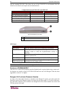
Features of P2-EUST/C
This device is an enhanced user station with a built-i
n card reader.
Its functions are similar to those of P2-EUST and can work with Paragon II that has been
upgraded to version 4.3 or higher. The internal card reader allows users to insert their smart cards
when prompted by the authentication software installed in the servers, and deliver the necessary
authentication data to the server. The P2-EUST/C is compatible with all CIMs that are compatible


