


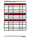
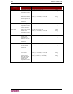


APPENDIX A: SPECIFICATIONS 127
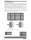
CAT5 Cable Guidelines
Use only straight-through-pinned four-pair (eight-wire) Category 5 unshielded twisted pair (UTP)
cables, terminated with standard RJ45 plugs, for the CAT5 cabling links in your Paragon system.
If your existing CAT5 site-wiring system meets these requirements, feel free to send the signals
through your site’s patch panels, existing wiring, etc., but you should keep the number of patches
and splices to a minimum to avoid degrading the video signals. Maximum end-to-end cabling
distance from any server to any user station should not exceed 1000 feet (304 m).
Please note that although users and servers can be located up to 1000 feet apart, for optimal video
quality, limit cable length between the user station and CIM to less than 100 feet (30.5 m). For
good video quality, limit cable length between the user station and CIM to less than 500 feet (152
m).
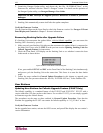
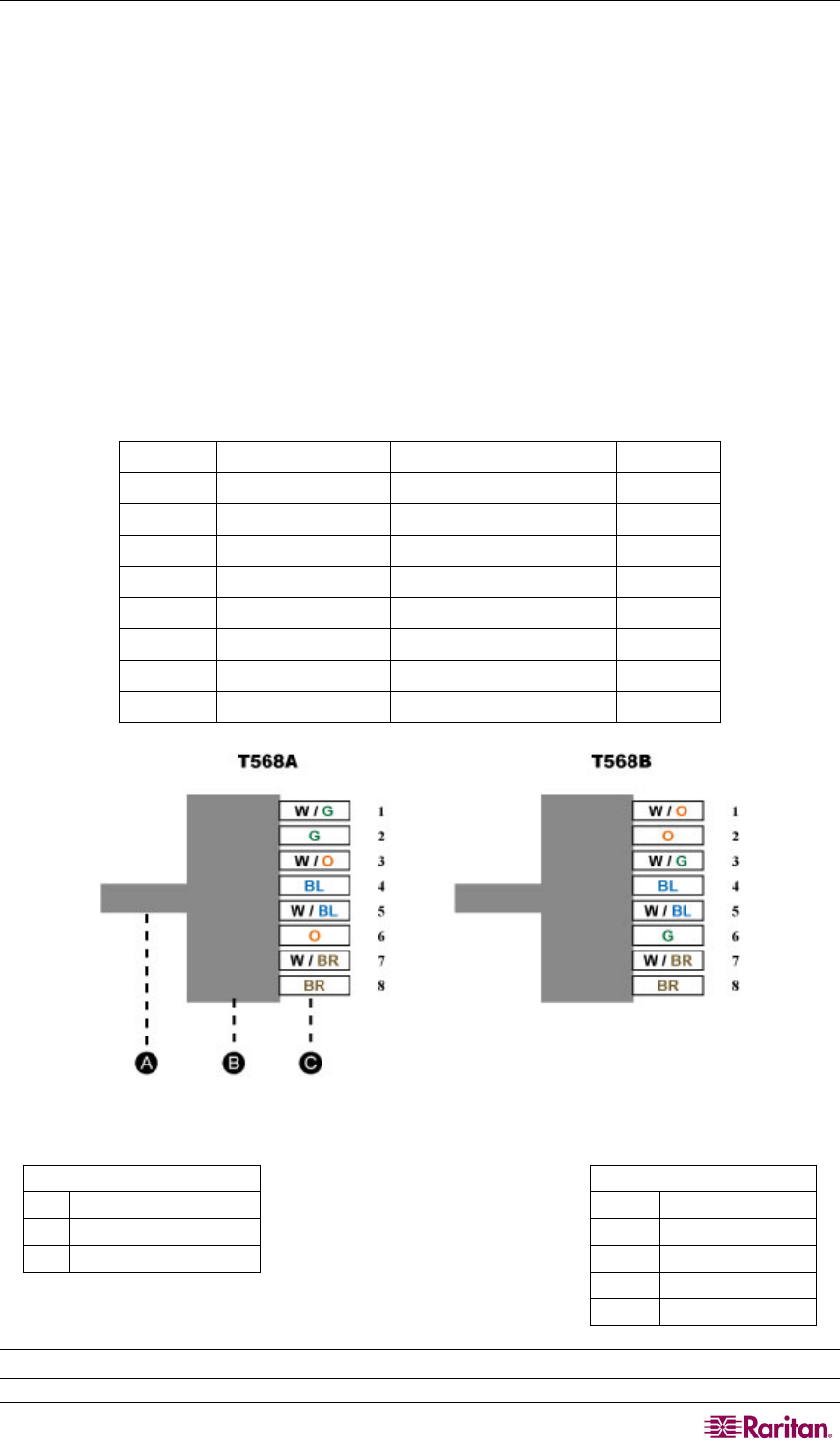
Looking into an RJ45 socket on any Paragon component, or looking at the cable plug from
behind with the tab on the bottom, Pin 1 should be on the left and Pin 8 on the right, and the wires
should be arranged this way, as per the TIA-568B standard:
Pin Color Function Pair
1 White/Orange TX (transmit signals) Pair 2
2 Orange/White RX (receive signals) Pair 2
3 White/Green TX Pair 3
4 Blue/White RX Pair 1
5 White/Blue TX Pair 1
6 Green/White RX Pair 3
7 White/Brown TX Pair 4
8 Brown/White RX Pair 4
Figure 103 Cat5 Cable Diagram
Part
Color
A
Cat5 cable
W
White
B
RJ45 connector
G
Green
C
Pin
O
Orange
BL
Blue
BR
Brown
Note: Use the configuration for the T568A OR the configuration for T568B.