


36 PARAGON II USER GUIDE
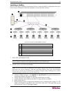
3. Connect the HubPac to each Paragon matrix switch by repeating all of the following steps for
each 5-port cluster on the HubPac:
Note: There are 8 five-port clusters on the HubPac. For each cluster the number in front of
the RJ45 IN port represents the cluster number. For example, cluster 1’s first RJ45 port is 1
IN, cluster 2’s is 2 IN, etc. In the instructions below, “X” represents the cluster number (1
through 8).
a. Connect one end of a Category 5e UTP cable to the RJ45 X-1 port on the back of the
HubPac.
b. Connect the other end of the cable to channel port # N on the back of one of the desired
Paragon switches.
c. Connect one end of a Category 5e UTP cable to the RJ45 X-2 port on the back of the
HubPac.
d. Connect the other end of the cable to channel port # N on the back of the second desired
Paragon switch.
e. Connect one end of a Category 5e UTP cable to the RJ45 X-3 port on the back of the
HubPac.
f. Connect the other end of the cable to channel port # N on the back of the third desired
Paragon switch.
g. Connect one end of a Category 5e UTP cable to the RJ45 X-4 port on the back of the
HubPac.
h. Connect the other end of the cable to channel port # N on the back of the fourth desired
Paragon switch.
4. Connect the power cord to the back of the HubPac. Power ON the HubPac
5. Power ON each of the Paragon switches.
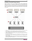
A HubPac can connect to 8 servers, and allows each server to be connected to 4 different Paragon
switches at once. Follow the above steps for each additional HubPac to be added.
Channel Configuration
Paragon recognizes a HubPac as an extension of a CIM, rather than as a device. As a result, each
server connected to the HubPac is configured as a directly connected server would be.
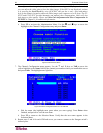
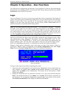
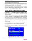
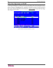
1. On the Selection Menu (by channel number) each green line indicates an active channel
(CIM/server). Highlight the CIM/server to be selected by using the Ç, È, or Page Up, Page
Down keys. Press Enter.
2. Normal server access indicates successful connection. If necessary, manually adjust the video
skew by pressing the + or - keys in the numeric keypad.
3. Enter a meaningful name for each server (channel).
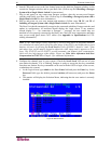
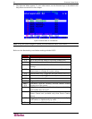
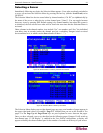
a. Press F5 for Administration Menu.
b. Select Channel Configuration with Ç or È keys and press Enter.
c. Press Ç or È to highlight (in yellow) the Name field for channel ID where CIM/server
was just installed. Press Enter. The highlight turns light blue.
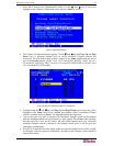
d. Edit the name (turns green when typing begins). Press Enter when completed.
e. Press S to save the new name.
f. Press F2 to return to Selection Menu (by channel number). Verify that new name appears
on Selection Menu in green.
4. Repeat for each CIM/server desired.