HOW-TO -- PARAGON ESSENTIALS 5
4. Depending on the configuration of the target server or authentication software, you may also
need to enter a PIN.
5. After the login authentication and authorization has been completed, you can start working on
the server.
6. When you complete your work, press the hot key (default: Scroll Lock) twice quickly to
trigger the On-Screen User Interface (OSUI).
>> Refer to: Using the OSUI for Initial Configuration section i
n Chapter 2 for details.
7. Press Shift +F9 to disconnect the server, and then remove the card.
>> Refer to: Using the Card Reader section in Chapter 3 for details.
The card’s au
thentication data is not stored in the Paragon system so you must repeat Steps 3 to 5
if you want to access the same server again.
Case 8. Creating Multiple Paths to the Same Server(s)
Purpose: To ensure that there is redundant access to specific servers. In this example, we will
create four available paths for access to specific servers using the structure of multiple Base Units.
Note: A Base Unit is a “first-tier” Paragon switch.
1. Prepare six Paragon switches, such as P2-UMT1664M and/or P2-UMT832M.
2. Choose three of them as Base Units, two as the 2
nd
tier, and one as the 3
rd
tier. If these
switches do not share the same firmware version, make sure the versions of lower tiers are
later than those of upper tiers. For example, Base Unit is with firmware version 4.2 and 2
nd
Tier with version 4.0.
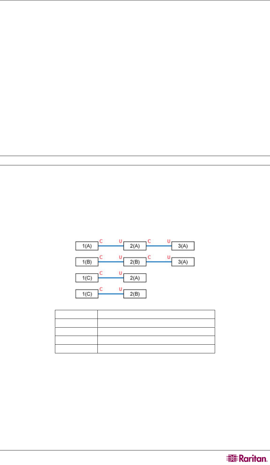
3. Connect all of these Paragon switches with Category 5 (Cat5) UTP cables from the channel
ports of lower tiers to user ports of upper tiers as illustrated below:
>> Refer to: Tiered Configurations section in Chapter 7 for details.
C
Channel ports
U
User ports
1(A) ~ 1(C)
Base Units (first-tier Paragon switches)
2(A) ~ 2(B)
Second-tier Paragon switches
3(A)
Third-tier Paragon switch


