


CHAPTER 7: CONFIGURATIONS 115
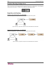
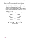
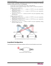
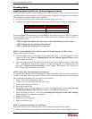
In order to make a redundant configuration system operate more efficiently, the following
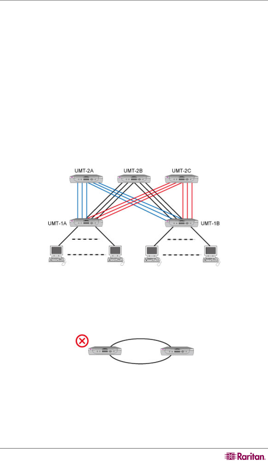
connection scheme between tiers is recommended:
− Assume there are two Paragon Base Units: UMT-1A and UMT-1B
− Assume there are three second-tier Paragon switches: UMT-2A, UMT-2B, and UMT-2C
− Channel connection of UMT-1A
Channel ports 3*N+1 (1, 4, 7….) connect to UMT-2A user ports sequentially,
starting from user port 1
Channel ports 3*N+2 (2, 5, 8….) connect to UMT-2B user ports sequentially,
starting from user port 1
Channel ports 3*N (3, 6, 9….) connect to UMT-2C user ports sequentially, starting
from user port 1
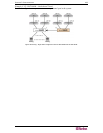
− Channel connection of UMT-1B
Channel ports 3*N+1 (1, 4, 7….) connect to UMT-2A user ports sequentially,
starting from the available user port.
Channel ports 3*N+2 (2, 5, 8….) connect to UMT-2B user ports sequentially,
starting from the available user port.
Channel ports 3*N (3, 6, 9….) connect to UMT-2C user port sequentially, starting
from the available user port.
Figure 98 Recommended Redundant Configuration Connection Scheme
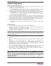
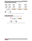
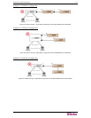
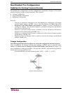
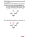
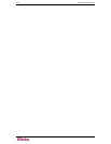
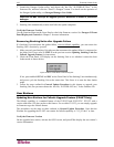
Loop-Back Configuration
This dead-loop setup will cause Server database conflict and should therefore never be used.
Figure 99 Illegal Loop-Back Configuration