


12
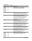
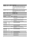
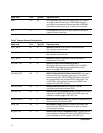
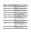
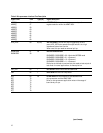
Signal name Pin # Type(I/O) Signal description
ADDR[0] 56 I ADDRESS BUS: Allows host microprocessor to perform
ADDR[1] 57 register selection within the HDMP-3001.
ADDR[2] 58
ADDR[3] 63
ADDR[4] 64
ADDR[5] 65
ADDR[6] 66
ADDR[7] 67
ADDR[8] 68
APS_INTB 83 O (O/D) APS INTERRUPT: Active-low output triggered by an APS
event. APS_INTB is an open-drain output which is in a high
impedance state when inactive.
When used, this pin needs an external pull-up.
BUSMODE0 87 I/O BUS INTERFACE MODE:
BUSMODE1 30
BUSMODE1, BUSMODE0 = 00 -> Motorola MPC860 mode
BUSMODE1, BUSMODE0 = 01 -> Reserved
BUSMODE1, BUSMODE0 = 10 -> Reserved
BUSMODE1, BUSMODE0 = 11 -> Reserved
Both pins are latched at reset and are also used as test outputs in
test mode. In normal applications, tie these pins low.
CPU_CLK 60 I CPU CLOCK: Used in Motorola MPC860 mode.
CSB 84 I CHIP SELECT: Active-low chip select.
D[0] 69 I/O I/O DATA BUS: Allows transfer of data between host
D[1] 72 microprocessor and the HDMP-3001.
D[2] 73 Refer to microprocessor application notes on the usage of
D[3] 74 board level pull-ups.
D[4] 75
D[5] 76
D[6] 77
D[7] 78
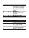
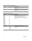
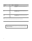
Table 4. Microprocessor Interface Pins Description
(continues)