


50
Bits 7-6: Reserved
Bit 5: SDA_PU_DIS disables the internal SDA pull-up when high.
Bit 4: SCL_PU_DIS disables the internal SCL pull-up when high.
Bits 3-2: Reserved
Bits 1-0: INT_MODE specifies the Microprocessor Interrupt Pin Mode which configures the INT (tristate)
output pin to support one of four modes: (1) 00: Default mode, Open-Drain, INT active level=0,
(2) 01: Not Recommended, Open-Source, INT active level=1, (3) 10: Always enabled, INT active
level=0, (4) 11: Always enabled, INT active level=1. Refer to Section 4.2.4, “Interrupt Modes of
HDMP-3001 µP Interrupt Output” for more information.
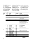
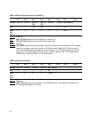
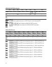
ADDR = 0x003: Microprocessor Interrupt Pin Mode[1:0]
Bit 7 Bit 6 Bit 5 Bit 4 Bit 3 Bit 2 Bit 1 Bit 0
Bit name Reserved Reserved SDA_PU_ SCL_PU_ Reserved Reserved INT_MODE[1:0]
DIS DIS
R/W —— R/W R/W ——R/W
Value 0 0 0 0 0 0 2'b00
after
reset
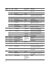
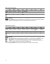
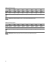
ADDR = 0x004: Chip Revision[3:0]
Bit 7 Bit 6 Bit 5 Bit 4 Bit 3 Bit 2 Bit 1 Bit 0
Bit name Reserved Reserved Reserved Reserved CHIP_REV[3:0]
R/W ————RO
Value 0 0 0 0 4'b0001
after
reset
Bits 7-4: Reserved
Bits 3-0: CHIP_REV specifies the chip revision of the HDMP-3001 chip. This register is the same as the
MII Management Register 3, bits [3:0].