


15
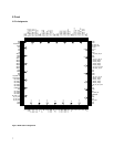
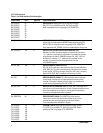
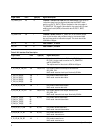
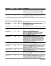
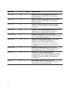
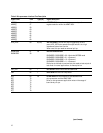
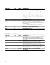
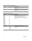
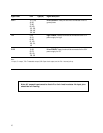
Signal name Pin # Type(I/O) Signal description
DGND 10, 11, 20, Driver GROUND: These pins should be connected to the I/O
40, 50, ground plane.
70, 80,
90, 100,
110, 120,
130, 140,
150, 160
VDD 2, 22, Logic POWER: These pins should be connected to the 1.8 V
42, 51, power supply for logic.
62, 82,
91, 102,
122, 131,
142
DVDD 19, 39, Driver POWER: These pins should be connected to the 3.3 V
59, 79, power supply for I/O.
99, 119,
139, 159
Note:
I = Input, O = output, T/S = Tristateable output, O/D = Open-drain output, and Int. PU = Internal pull-up.
Note: All unused inputs must be tied off to their inactive states. No input pins
should be left floating.