


36
high-speed device that locates
frame, does byte de-interleaving,
and performs serial-to-parallel
conversion of an STS-3c/STM-1
signal.
3.9.4.11 Framer Enabled Details
If the framer is enabled
(RX_FRMR_INH = 0), the
HDMP-3001 device performs the
framer processing as follows.
When the framer state machine is
out-of-frame (RX_OOF = 1), it
searches for the 32-bit A1-A1-A2-
A2 framing byte sequence of
0xF6F6_2828. This pattern may
start on any of the 8 input data
lines and span up to five input
bytes. When the framer finds two
successive sequences separated in
time by 125 µs that exactly match
the framing pattern, it goes into
frame (RX_OOF = 0) and byte
aligns its output data bus. The
framer remains in-frame, until it
receives five successive frames
with at least one bit error in the
A1-A1-A2-A2 framing pattern.
When this occurs, RX_OOF is set
to one, and a new frame search is
begun. The framer also provides a
loss-of-frame indication. If
RX_OOF is active (high) continu-
ously for 24 consecutive frames
(3 ms), the RX_LOF bit is set to
one. Once RX_LOF is set, it re-
mains high until RX_OOF is
inactive (low) continuously for
either 24 (if RX_LOF_ALG = 0) or
8 (if RX_LOF_ALG = 1) consecu-
tive frames.
The out-of-frame and loss-of-
frame indications are also
available as HDMP-3001 output
pins, RX_OOF_OUT and
RX_LOF_OUT. The RX_OOF_D
and RX_LOF_D delta bits contrib-
ute to the summary interrupt. The
framer also outputs the
RX_FRAME_OUT signal. This sig-
nal is nominally 8 kHz and is high
during the first row of overhead
of the received frame. The
RX_FRAME_OUT signal is also
used for byte alignment of the re-
ceived E1, E2, and F1 data
outputs.
3.9.4.12 Framer Bypass Details
If the framer is bypassed
(RX_FRMR_INH = 1), an external
framer must supply the HDMP-
3001 with a start of frame
indication, RX_FRAME_IN. The
HDMP-3001 sets its internal frame
counter when the RX_FRAME_IN
input transitions from 0 to 1. The
relationship of the start of frame
to the 0 to 1 transition of
RX_FRAME_IN is set through the
RX_FRAME_POSITION[3:0] in
register 0x101.
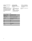
3.9.4.13 Descrambling
For transmitting direction, the
STM-N (N = 0, 1, 4, 16, 64, 256)
signal must have sufficient bit tim-
ing content at the NNI. A suitable
bit pattern, which prevents a long
sequence of ones or zeros, is pro-
vided by using a scrambler.
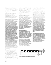
The STM-N (N = 0, 1, 4, 16, 64,
256) signal shall be scrambled
with a frame synchronous scram-
bler of sequence length 127
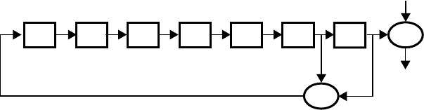
operating at the line rate.The gen-
erating polynomial shall be
1 + X
6
+ X
7
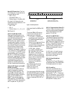
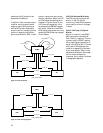
. Figure 17 gives a
functional diagram of the frame
synchronous scrambler.
The scrambler is reset to all ones
on receipt of the most significant
bit of the byte following the last
byte of the first row of the STM-N
SOH. This bit, and all subsequent
bits to be scrambled are added
modulo 2 to the output from the
X
7
position of the scrambler. The
scrambler runs continuously
throughout the complete STM-N
frame. The first row of the STM-N
(N x 64), SOH (9 x N bytes, 3
bytes for STM-0, including the A1
and A2 framing bytes) are not
scrambled. So, in the receive di-
rection, in either framer enabled
or framer bypass mode, before
the data is output it can be de-
scrambled using the same frame
synchronous sequence that is
used to scramble the transmit
data.
The descrambler is reset to all
ones at the beginning of the first
SPE/ VC byte (the byte in column
10 of row 1), and it descrambles
the entire SONET/SDH signal ex-
cept for the first row of TOH/SOH.
For testing purposes, the
descrambler can be disabled by
setting DSCRINH to one.
Figure 17. Functional block of SONET framer scrambler
D1 D2 D3 D4 D5 D6 D7
XOR
INPUT
OUTPUT
XOR