42
5. Register Definitions
The HDMP-3001 contains two reg-
ister maps. One is the MII
Management (MDIO) register
map, which can only be accessed
through the MDIO port. The other
register map is the chip register
map which can be accessed
through the MDIO, microproces-
sor and EEPROM ports.
5.1 MII Management Register Map
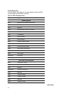
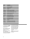
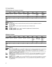
The MII Management register map,
Table 21, is only accessible
through the MII Management port.
It is defined in the IEEE 802.3
specification, and is used to re-
port the capabilities and
identification of the HDMP-3001
when used as a PHY. The registers
on address 16 and 17 provide a
path to the complete chip memory
map through indirect addressing.
To write a chip register, first write
the chip register address to regis-
ter 16 and then write the value to
register 17. To read a chip regis-
ter, first write the chip register
address to register 16 and then
read the value of register 17.
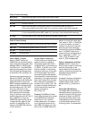
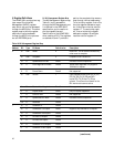
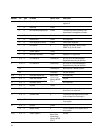
Address Bit Type Bit Name Default value Description
0 15 R/W Reset 0 Reset PHY. This bit clears automatically
when reset is complete.
14 R/W Loopback 0 Loopback on/off. Default off.
13 R Speed Selection LSB Fixed 1 Indicates 100 Mb/s operation
12 R Auto-Negotiation Enable Fixed 0 Cannot auto-negotiate, only supports
100 Mb/s full-duplex.
11 R Power Down Fixed 0 Not supported.
10 R/W Isolate 1 High impedance state is set on TX_CLK,
RX_CLK, RX_DV, RX_ER and RXD.
Inputs TXD, TX_EN and TX_ER are
ignored. This bit must be cleared for the
MII interface to become active.
9 R Restart Auto-Negotiation Fixed 0 Not supported.
8 R Duplex Mode Fixed 1 Only full duplex supported.
7 R Collision Test Fixed 0 Not supported.
6 R Speed selection MSB Fixed 0 Indicates 100 Mb/s operation
5-0 R Reserved Fixed 0
1 15 R 100BASE-T4 Fixed 0
14 R 100BASE-X Full Duplex Fixed 1 Supports only 100BASE-X full duplex.
13 R 100BASE-X Half Duplex Fixed 0
12 R 10 Mb/s Full Duplex Fixed 0
11 R 10 Mb/s Half Duplex Fixed 0
10 R 100BASE-T2 Full Duplex Fixed 0
9 R 100BASE-T2 Half Duplex Fixed 0
Table 18. MII Management Register Map
(continues)


