


13
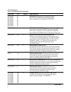
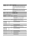
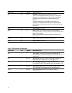
Signal name Pin # Type(I/O) Signal description
INT 86 O (T/S) INTERRUPT: Configurable interrupt output. Refer to
Table 18 for a detailed description of how INT is configured.
In open-drain configurations, an external pull-up is required.
In open-source configurations, an external pull-down is
required.
To prevent undesired interrupts before configuration is
complete, microprocessors with an active-high interrupt pin
should have a pull-down and those with an active-low interrupt
pin, a pull-up.
RDB 55 I READ ENABLE: Active low.
RDYB 53 I/O READY: RDYB is an active-low output to acknowledge the
end of data transfer. This pin is briefly driven to its inactive state
before being tristated.
Refer to microprocessor application notes for board pull-up
requirements.
RSTB 85 I RESET: Active low input to reset the HDMP-3001.
WRB 54 I WRITE ENABLE: Active low.
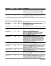
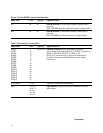
Signal name Pin # Type(I/O) Signal description
TCK 7 I TEST CLOCK: JTAG input clock used to sample data on the
TDI and TDO pins. Should be tied high when the JTAG interface
is not in use.
TDI 8 I (Int PU) TEST DATA IN: Input pin for serial data stream to be sent to
HDMP-3001. TDI is sampled on the rising edge of TCK.
TDO 6 O TEST DATA OUT: Output pin for serial data stream sent
from the HDMP-3001. TDO is sampled on the falling edge of` TCK.
TMS 5 I (Int. PU) TEST MODE SELECT: Controls the operating mode of the
JTAG interface. TMS is sampled on the rising edge of TCK.
TRSTB 4 I (Int. PU) TEST PORT RESET: Active low input used to reset the
JTAG interface.
Table 5. JTAG Interface Pins Description