


34
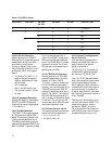
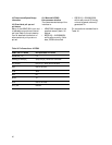
Norm_point: Normal NDF AND match of ss bits AND offset value in range.
NDF_enable: NDF enabled AND match of ss bits AND offset value in range.
AIS_ind: 11111111 11111111.
Incr_ind: Normal NDF AND match of ss bits AND majority of I bits inverted AND no majority of
D bits inverted AND previous NDF_enable, incr_ind or decr_ind more than three frames ago.
Decr_ind: Normal NDF AND match of ss bits AND majority of D bits inverted AND no majority
of I bits inverted AND previous NDF_enable, incr_ind or decr_ind more than three frames ago.
Inv_point: Any other state OR norm_point with offset value not equal to active offset.
Table 13. Pointer Processing
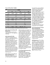
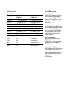
Norm_point: Normal NDF AND match of ss bits AND offset value in range.
Conc_ind: NDF enabled and pointer value = 1111111111
AIS_ind: 11111111 11111111
Inv_point: Any other state
Table 14. Pointer Tracking
3.9.4.9.2 SONET J1 Capture
When in SONET mode, the
HDMP-3001 can be provisioned to
capture a sample of the path trace
message. When J1_READ transi-
tions from 0 to 1, the HDMP-3001
captures 64 consecutive J1 bytes
from the specified tributary and
writes them to RX_J1[63:0]_[7:0].
No path trace frame structure is
defined for SONET, but GR-253
does recommend that the 64-byte
sequence consist of a string of
ASCII characters padded out to 62
bytes with NULL characters (00)
and terminated with <CR> (0D)
and <LF> (0A) bytes. If the
J1_MODE bit is set, the HDMP-
3001 captures the first 64 byte
string it receives in the J1 byte
position that ends with {0D, 0A}. If
the J1_MODE bit is zero, the
HDMP-3001 captures the next 64
J1 bytes without regard to their
content. On completion of the
capture, the HDMP-3001 sets the
J1_AVL event bit.
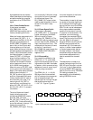
3.9.4.9.3 16-Byte J1 Monitoring
In SDH mode, the J1 bytes are ex-
pected to contain a repeating
16-byte path trace frame that in-
cludes the PAPI. In this mode, the
J1_READ, J1_MODE, and J1_AVL
bits are not used. J1 monitoring
consists of locking on to the start
of the 16-byte path trace frame
and examining the received path
trace frames for values that match
consistently for three consecutive
path trace frames. When a consis-
tent frame value is received, it is
written to RX_J1[15:0]_[7:0]. The
first byte of the path trace frame
(which contains the frame start
marker) is written to
RX_J1[15]_[7:0].
Framing. The MSBs of all path
trace frame bytes are zero, except
for the MSB of the frame start
marker byte. The J1 monitor
framer searches for 15 consecu-
tive J1 bytes that have a zero in
their MSB, followed by a J1 byte
with a one in its MSB. When this
pattern is found, the framer goes
into frame, J1_OOF = 0. Once the
J1 monitor framer is in frame, it
remains in frame until three con-
secutive path trace frames are
received with at least one MSB bit
error. (In SONET mode, the J1
frame indication is always held in
the in frame state, J1_OOF = 0.)
The J1_OOF_D delta bit is set
when J1_OOF changes state.
Pattern Acceptance and Com-
parison. Once in frame, the J1
monitor block looks for three con-
secutive 16-byte path trace
frames. When three consecutive
identical frames are received, the
accepted frame is stored in
RX_J1[15:0]_[7:0].
Accepted frames are compared to
the previous contents of these
registers. When a new value is
stored, the RX_J1_D delta bit is
set.
3.9.4.9.4 BIP-8 (B3) Checking
The HDMP-3001 checks the re-
ceived B3 bytes for correct BIP-8
values. Even parity BIP-8 is calcu-
lated over all bits in the SPE/VC
(including the POH) each frame.
These values are then compared
to the B3 values received in the
following frame. The comparison