


18
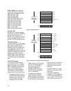
3.2.5 SONET/SDH Interface
This interface is 8 bits wide and
runs at 19.44 MHz. The Serial
SONET/SDH overhead channels
are clocked in and out of the IC
through low-speed serial ports.
3.3 Initialization
3.3.1 Hardware reset
The HDMP-3001 hardware reset,
RSTB, is asynchronous and must
be active for at least 200 SONET
clock cycles (>10 µs) with stable
power.
TX_DATA[7]
TX_DATA[6]
TX_DATA[5]
TX_DATA[4]
TX_DATA[3]
TX_DATA[2]
TX_DATA[1]
TX_DATA[0]
7
6
5
4
3
2
1
0
7
6
5
4
3
2
1
0
0
1
2
3
X
7
S
C
R
G
F
P
M
I
I
I
/
F
X
4
3
S
C
R
C
R
C
G
E
N
7 6 5 4 3 2 1 0
F
L
[7] [0]
7 6 5 4 3 2 1 0
F
L
7 6 5 4 3 2 1 0
F
L
LSN
F
4
5
6
7
MSN
L
PINS
PINS
TXD0
TXD1
TXD2
TXD3
F = FIRST
L = LAST
3.3.2 Software Reset
Software resets are functionally
equivalent to hardware resets.
There are two identical software
resets, one in the microprocessor
register map and one in the MII
register map. Both resets are self-
cleared in less than 10 µs.
3.3.3 Software State Machine Reset
This reset should always be active
when the chip is configured. Only
when the configuration is com-
pleted should the state machine
reset be cleared to begin normal
operation.
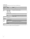
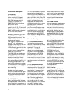
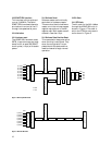
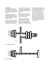
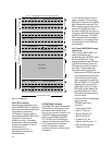
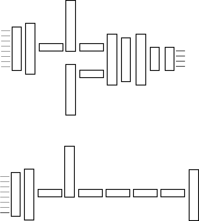
3.4 Bit Order
3.4.1 GFP Mode
The bit order for the MII nibbles
through the HDMP-3001 chip is
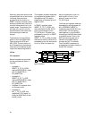
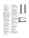
shown in Figure 4. The order in
which the FCS bits are transmit-
ted is shown in Figure 5.
TX_DATA[7]
TX_DATA[6]
TX_DATA[5]
TX_DATA[4]
TX_DATA[3]
TX_DATA[2]
TX_DATA[1]
TX_DATA[0]
7
6
5
4
3
2
1
0
X
7
S
C
R
X
4
3
S
C
R
C
R
C
G
E
N
7 6 5 4 3 2 1 0
F
L
[7] [0]
PINS
7 6 5 4 3 2 1 0
F
X
31
X
24
7 6 5 4 3 2 1 0
X
23
X
16
7 6 5 4 3 2 1 0
X
15
X
8
7 6 5 4 3 2 1 0
L
X
7
X
0
Figure 4. GFP Payload Bit Order
Figure 5. GFP FCS Bit Order