


29
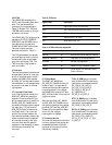
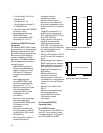
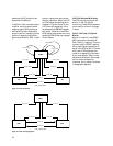
Non-AIS Generation. The first
H1-H2 byte pair is transmitted as
a normal pointer with:
• NDF = 0110
• SS (SONET/SDH) = 0
• Pointer Value = 10_0000_1010
All other H1-H2 byte pairs are
transmitted as concatenation indi-
cation bytes, with
• NDF =1001
• SS = 0
• Pointer Value = 11_1111_1111.
See Figure 14.
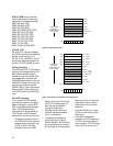
3.9.3.3.9 Line/MS BIP-24 (B2)
There are three B2 bytes in the
TOH/SOH, and together they pro-
vide a BIP-24 error detection
capability. Each B2 byte provides
BIP-8 parity over bytes in one of
three groups of bytes in the previ-
ous frame. The B2 byte in column
j provides BIP-8 parity over bytes
in the previous frame (except
those in the first three rows of
TOH/SOH) that appear in columns
j + 3k, where k = 0 through 89 and
j = 0 through 2. The BIP-8 is trans-
mitted as even parity (normal) if
B2_INV = 0. Otherwise, odd parity
(incorrect) is generated. The BIP-
8 values are calculated over bytes
in the previous STS-3c/STM-1
frame before scrambling and
placed into the B2 bytes of the
current frame before scrambling.
3.9.3.3.10 APS Channel and Line/MS
AIS/RDI (K1 and K2)
K1 and the five MSBs of K2 are
used for automatic protection
switching (APS) signaling. The
three LSBs of K2 are used as an
AIS or Remote Defect Indication
(RDI) at the line/MS level. In
SONET, they are also used for
APS signalling. The HDMP-3001
inserts TX_K1[7:0] in the transmit-
ted K1 bytes and TX_K2[7:3] in
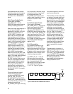
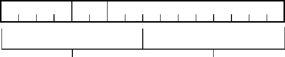
NEW DATA FLAG (NOF)
NNNNSS IDIDIDIDID
1234567812345678
SS BITS
10--BIT POINTER VALUE
MSB
LSB
BIT
H1 BYTE
H2 BYTE
NDF DISABLED: 0110
NDF ENABLED: 1001
POSITIVE STUFF: INVERT 5 I-BITS
NEGATIVE STUFF: INVERT 5 D-BITS
Figure 14. Pointer Byte Fields
the transmitted five MSBs of K2
bytes.
The three LSBs of K2 are con-
trolled from three sources. In
order of priority, these are
• if TX_LAIS = 1, the bits are
transmitted as all ones (as are
all line/MS overhead bytes)
indicating LAIS.
• if bits 6 to 8 of received K2 are
111, the three LSBs of the
transmit K2 are transmitted as
all ones indicating LRDI.
• if LRDI_INH = 0 and if
any of (RX_LOS AND NOT
RX_LOS_INH), RX_LOF and
RX_LAIS =1, the bits are
transmitted as 110 indicating
LRDI. Any time this particular
event is active, the three LSBs
of K2 are set to 110 for a
minimum of 20 frames.
• otherwise TX_K2[2:0] is
transmitted.
RX_LOS can be active high
(RX_LOS_LEVEL = 0, the
default) or active low
(RX_LOS_LEVEL = 1).
The requirements R6-180 through
R6-182 of GR-253 specify that RDI
should be inserted and removed
within 125 µs of detection and re-
moval of received LOS, LOF, or
LAIS.
3.9.3.3.11 Synchronization Status (S1)
The four LSBs of this byte convey
synchronization status messages.
The transmitted S1 byte is set
equal to TX_S1[7:0].
3.9.3.3.12 Line/MS REI (M1)
The Receive Side monitors B2 bit
errors in the received signal. The
number of B2 errors detected in
each frame can range from 0 to 24
B2 bits. The line/MS Remote Error
Indication (REI) byte, the M1
byte, normally conveys the count
of B2 errors detected in the re-
ceived signal.
If LREI_INH = 0, the M1 byte is
set equal to the most recent B2
error count. Otherwise, the M1
byte is set to all zeros.
3.9.3.3.13 Growth/Undefined
(Z1 and Z2)
The use of the Z1 and Z2 bytes is
not standardized. The HDMP-3001
fills these bytes with all zeros.
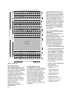
3.9.3.4 Scrambling
The input is scrambled with a
frame synchronous scrambling
sequence generated from the
polynomial X
7
+X
6
+1. The scram-
bler is initialized to 1111111 at the
beginning of the first SPE/VC byte
(the byte in column 10 of row 1 in
STS-3c/STM-1 mode), and it