


26
3.9.3.2 POH
There are nine bytes of path over-
head. The first byte of the path
overhead is the path trace byte,
J1. Its location with respect to the
SONET/SDH TOH/SOH is indi-
cated by the associated STS/AU
pointer. The following sections
define the transmitted values of
the POH bytes. Where the byte
names differ between SONET and
SDH, the SONET name is listed
first.
3.9.3.2.1 Path Trace (J1)
The HDMP-3001 can be pro-
grammed to transmit either a
16-byte or a 64-byte path trace
message in the J1 byte. The mes-
sages are stored in
TX_J1[63:0]_[7:0]. In SDH mode,
the J1 byte is transmitted repeti-
tively as the 16-byte sequence in
TX_J1[15]_[7:0] down to
TX_J1[0]_[7:0]. Otherwise, the
64-byte sequence in
TX_J1[63]_[7:0] down to
TX_J1[0]_[7:0] is transmitted.
(The 16-byte sequence is used in
the SDH mode, and the 64-byte
sequence in the SONET mode.)
3.9.3.2.2 Path BIP-8 (B3)
The Bit Interleaved Parity 8 (BIP-
8) is transmitted as even parity
(normal) if register bit B3_INV =
0. Otherwise, odd parity (incor-
rect) is generated. The BIP-8 is
calculated over all bits of the pre-
vious SPE/VC (including the POH)
before scrambling and placed into
the B3 byte of the current SPE/VC
before scrambling. By definition
of BIP-8, the first bit of B3 pro-
vides parity over the first bit of all
bytes of the previous SPE/VC, the
second bit of B3 provides parity
over the second bit of all bytes of
the previous SPE/VC, etc.
3.9.3.2.3 Signal Label (C2)
The signal label byte indicates the
composition, e.g. LAPS or GFP, of
the SPE/VC. The provisioned
value, TX_C2[7:0], is inserted into
the generated C2 bytes.
3.9.3.2.4 Path Status (G1)
The receive side monitors B3 bit
errors in the received SPE/VC.
The number of B3 errors detected
in each frame (0 to 8) is trans-
ferred from the receive side to the
transmit side for insertion into the
transmit path status byte, G1, as a
Remote Error Indication. If regis-
ter bit PREI_INH = 0, the bits are
set to the binary value (0000
through 1000, indicating between
0 and 8) equal to the number of
B3 errors most recently detected
by the Receive Side POH monitor-
ing block. Otherwise, they are set
to all zeros.
Path RDI. Bit 5 of G1 can be used
as a Path/AU Remote Defect Indi-
cation, RDI-P, or bits 5, 6, and 7 of
G1 can be used as an enhanced
RDI-P indicator. The values trans-
mitted in bits 5, 6, and 7 of G1 are
taken either from the TX_G1[2:0]
registers (if PRDI_AUTO = 0), or
the HDMP-3001 automatically
generates an enhanced RDI signal
(if PRDI_AUTO = 1 and
PRDI_ENH = 1), or a one bit RDI
signal (if PRDI_AUTO = 1 and
PRDI_ENH = 0). The values trans-
mitted in bits 5, 6, and 7 of G1 are
shown in Table 11.
If PRDI_AUTO = 1, the values
shown above are transmitted for a
minimum of 20 frames. Once 20
frames have been transmitted
with the same value, the value
corresponding to the current state
of the defect indication values
listed in Table 1 will be transmit-
ted. Bit 8 of G1 (the LSB) is
unused, and it is set to zero.
3.9.3.2.5 Other POH Bytes
The remaining POH bytes are not
supported by the HDMP-3001 and
are transmitted as all zeros. These
include the path user channel
(F2), the position indicator (H4),
the path growth/user channel (Z3/
F3), the path growth/path APS
channel (Z4/K3), and the tandem
connection monitoring (Z5/N1)
bytes.
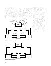
3.9.3.2.6 SONET/SDH Frame
Generation
The SONET/SDH frame generator
creates an STS-3c/STM-1 by gen-
erating the Transport (Section)
Overhead (TOH/SOH) bytes, fill-
ing the payload with bytes from
SPE/VC, and scrambling all bytes
of the SONET/SDH signal except
for the first row of TOH/SOH
bytes.
3.9.3.2.7 Frame Alignment
HDMP-3001 does not support
frame alignment in the transmit
direction.
3.9.3.2.8 Payload Generation
The SONET or SDH payload is
normally filled with bytes from
the SPE/VC. The J1 byte of the
SPE/VC is placed into column 10
of row 1.