


21
3.6.2 JTAG
The HDMP-3001 supports the
IEEE 1149.1 Boundary Scan stan-
dard. The Test Access Port
consists of 5 pins as defined in
Table 10. Signals TDI, TMS and
TRSTSB are all pulled up to logic
one when not driven.
The HDMP-3001 TAP supports the
mandatory EXTEST, SAMPLE/
PRELOAD, and BYPASS instruc-
tions along with the optional
CLAMP and HIGHZ instructions.
The instructions and their
opcodes are listed in Table 11.
The TAP generates a two-phase
non-overlapping clock to control
the boundary scan chain based
upon the input signal TCK. The
TAP controller is optimized to
work at 10 MHz.
3.7 Interrupts
The microprocessor interface can
be operated in either an interrupt
driven or a polled mode. In both
modes, the HDMP-3001 register
bit SUM_INT can be used to deter-
mine whether or not changes have
occurred in the state of monitor-
ing registers.
3.7.1 Interrupt Driven Mode
In an interrupt driven mode, the
SUM_INT_MASK bit should be
cleared. This allows the INT out-
put to become active. In addition,
the RX_APS_INT_MASK bits of
the receive side should be cleared
(to logic zero). This allows the
APS_INTB output to become ac-
tive (logic zero). If an interrupt
occurs, the microprocessor can
first read the summary status reg-
isters to determine the class(es)
of interrupt source(s) that is ac-
tive, and then read the specific
registers in that class(es) to deter-
mine the exact cause of the
interrupt.
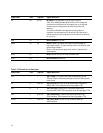
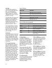
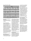
Instruction Opcode Description
EXTEST 00 Board Level Interconnection Testing
SAMPLE/ PRELOAD 02 Snapshots of Normal Operation
BYPASS FF Normal Chip Operation
HIGHZ 08 Outputs in High Impedance State
CLAMP 04 Holds Values from Boundary-Scan
Chain to Outputs
Table 10. JTAG instructions supported
3.7.2 Polled Mode
The SUM_INT_MASK and
RX_APS_INT_MASK bits should
be set to logic 1 to suppress all
hardware interrupts and operate
in a polled mode. In this mode,
the HDMP-3001 outputs INT and
APS_INTB are held in the inactive
(logic one) state.
Note that the SUM_INT_MASK
and RX_APS_INT_MASK bits do
not affect the state of the register
bits SUM_INT and RX_APS_INT.
These bits can be polled to deter-
mine if further register
interrogation is needed.
3.7.3 Interrupt Sources
The interrupt sources are divided
into four groups. Each group can
be masked and each interrupt
source within the group can be
individually masked.
TOH_D_SUM group indicates
that at least one of the delta sig-
nals below is unmasked and set.
RX_LOS_D, RX_OOF_D,
RX_LOF_D, RX_LAIS_D,
RX_LRDI_D, RX_K1_D,
K1_UNSTAB_D,
RX_K2_D, J0_OOF_D
PTR _D_SUM group indicates
that at least one of the delta sig-
nals below is unmasked and set.
RX_PAIS_D, RX_LOP_D
PATH_D_SUM group indicates
that at least one of the delta sig-
nals below is unmasked and set.
RX_PLM_D, RX_UNEQ_D,
RX_G1_D, RX_C2_D, J1 _AVL,
J1_OOF_D
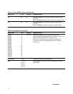
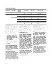
Signal Name Description
TDI Signal input to the TAP controller
TMS TAP controller state machine control
TCK TAP controller clock
TRSTB Asynchronous TAP reset
TDO Scan output from TAP
Table 9. JTAG pins