


52
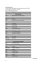
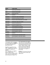
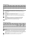
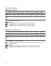
ADDR=0x007: Event Summary
Bit 7 Bit 6 Bit 5 Bit 4 Bit 3 Bit 2 Bit 1 Bit 0
Bit name TOH_D_SUM Reserved PTR_D_SUM POH_D_SUM Reserved EOS_D_SUM Reserved Reserved
R/W R — RRRR——
Value 0 0000000
after
reset
Bit 7: TOH_D_SUM is set to indicate at least one of the TOH/SOH delta bits (RX_LOS_D,
RX_OOF_D, RX_LOF_D, RX_LAIS_D, RX_LRDI_D, J0_OOF_D) is set and its corresponding
mask bit is cleared.
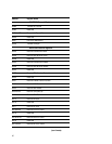
Bit 6: Reserved
Bit 5: PTR_D_SUM is set to indicate at least one of the Pointer Interpreter delta bits (RX_PAIS_D,
RX_LOP_D) is set and its corresponding mask bit is cleared.
Bit 4: POH_D_SUM is set to indicate at least one of the Path Monitoring delta bits (RX_PLM_D,
RX_UNEQ_D, RX_G1_D, J1_OOF_D, J1_AVL, RX_C2_D) is set and its corresponding mask is
cleared.
Bit 3: Reserved
Bit 2: EOS_D_SUM is set to indicate at least one of the delta signals (NEW_RX_OOS_ERR,
NEW_RX_FORM_DEST_ERR, NEW_RX_FIFO_UR_ERR, NEW_RX_FIFO_OF_ERR,
NEW_RX_FCS_HEC_ERR, NEW_TX_FIFO_UR_ERR, NEW_TX_FIFO_OF_ERR,
NEW_TX_ER_ERR, NEW_TX_MII_ALIGN_ERR) is set and enabled.
Bits 1-0: Reserved
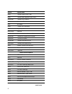
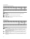
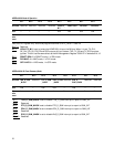
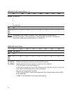
Bits 7-3: Reserved
Bit 2: GROUP_APS_INTB: If 1, it sets all unmasked RX_APS_INT alarms, SUM_INT bit and APS_INT
pin. This mode is useful in configuration where only one interrupt line on the CPU is used and is
connected to the INTB pin. If 0, it inhibits the RX_APS_INT alarms from affecting the SUM_INT bit.
This mode is useful in configuration where APS_INT and INTB are connected to separate interrupt
lines.
Bit 1: RX_APS_INT_MASK is set to enable the HDMP-3001 interrupt output pin APS_INTB.
Bit 0: SUM_INT_MASK is set to enable the HDMP-3001 interrupt output pin INTB.
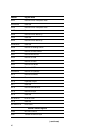
ADDR=0x008: Summary Interrupt Mask
Bit 7 Bit 6 Bit 5 Bit 4 Bit 3 Bit 2 Bit 1 Bit 0
Bit name Reserved Reserved Reserved Reserved Reserved GROUP_ RX_APS_INT_ SUM_INT_
APS_INTB MASK MASK
R/W —— — — —R/W R/W R/W
Value 00 0 0 01 1 1
after
reset