


32
• If PTR_STATE[1:0] = 00
and {LOP2,AIS2} = 11 and
{LOP3,AIS3} = 11, which is the
normal case, then RX_PAIS = 0
and RX_LOP = 0.
• If PTR_STATE[1:0] = 01
and {LOP2,AIS2} = 01 and
{LOP3,AIS3} = 01, then
RX_PAIS = 1 and RX_LOP = 0.
• If PTR_STATE[1:0] = 10
and {LOP2,AIS2} = 01 and
{LOP3,AIS3} = 10, then
RX_PAIS = 0 and RX_LOP = 1.
The RX_PAIS and RX_LOP signals
contribute to the Path Remote De-
fect Indication (PRDI). Changes in
these state values are indicated by
the RX_PAIS_D and RX_LOP_D
delta bits.
3.9.4.7 Pointer Interpretation
The first H1-H2 byte pair is inter-
preted to locate the start of the
SPE/VC. The rules for pointer
interpretation are:
1. During normal operation, the
pointer locates the start of the
SPE/VC.
2. Any variation from the current
accepted pointer is ignored
unless a consistent new value
is received three times
consecutively, or it is preceded
by one of the rules 3, 4, or 5.
Any consistent new value
received three times
consecutively overrides rules 3
or 4.
3. In the case of SONET mode, if
at least three out of four of the
NDF bits match the disabled
indication (0110) and at least 8
out of 10 of the pointer value
bits match the current accepted
pointer with its I-bits inverted,
a positive justification is
indicated. The byte following
the H3 byte is considered a
positive stuff byte, and the
current accepted pointer value
is incremented by 1 (mod 783).
In the case of SDH mode, if at
least three out of four of the
NDF bits match the disabled
indication (0110), three or
more of the pointer value I-bits
and two or fewer of the
pointer value D-bits match the
current accepted pointer with
all its bits inverted, and either
the received SS-bits are 10 or
RX_SS_EN = 0, a positive
justification is indicated. The
byte following the H3 byte is
considered a positive stuff
byte, and the current accepted
pointer value is incremented
by 1 (mod 783).
4. In the case of SONET mode, if
at least three out of four of the
NDF bits match the disabled
indication (0110) and at least
eight out of ten of the pointer
value bits match the current
accepted pointer with its
D-bits inverted, a negative
justification is indicated. The
H3 byte is considered a negative
stuff byte (it is part of the
SPE), and the current accepted
pointer value is decremented
by 1 (mod 783).
In the case of SDH mode, if at
least three out of four of the
NDF bits match the disabled
indication (0110), three or
more of the pointer value D-
bits and two or fewer of the
pointer value I-bits match
the current accepted pointer
with all its bits inverted, and
either the received SS-bits are
10 or RX_SS_EN = 0, a negative
justification is indicated. The
H3 byte is considered a
negative stuff byte (it is part of
the VC), and the current
accepted pointer value is
decremented by 1 (mod 783).
5. In the case of SONET mode,
if at least three out of four of
the NDF bits match the
enabled indication (1001), and
the pointer value is between 0
and 782, the received pointer
replaces the current accepted
pointer value. For SDH mode,
if at least three out of four of
the NDF bits match the
enabled indication (1001), the
pointer value is between 0 and
782, and either the received
SS-bits are 10 or RX_SS_EN =
0, the received pointer
replaces the current accepted
pointer value. Using these
pointer interpretation rules,
the Pointer Interpreter block
determines the location of
SPE/VC payload and POH
bytes.
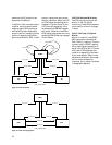
3.9.4.8 Pointer Processing
The pointer tracking algorithm
implemented in the HDMP-3001
device is illustrated in Figure 16.
Please refer to G.783 and GR-253
for definitions of the transitions.
The pointer tracking state ma-
chine is based on the pointer
tracking state machine found in
the ITU-T requirements, and is
also valid for both Bellcore and
ANSI. The AIS to LOP transition
of the state machine does not oc-
cur in Bellcore mode (i.e., the
BELLCORE bit is set to logic one).
For STM-1/STS-3c operation, the
pointer is a binary number with
the range of 0 to 782 (decimal). It
is a 10-bit value derived from the
two least significant bits of the H1
byte, with the H2 byte concat-
enated, to form an offset in 3-byte
counts from the H3 byte location.
For example, for an STM-1 signal,
a pointer value of zero indicates
that the VC-4 starts in the byte lo-
cation three bytes after the H3
byte, whereas an offset of 87 indi-