


33
cates that the VC-4 starts three
bytes after the K2 byte.
In addition, 8-bit counters are pro-
vided for counting positive and
negative justification events, as
well as NDF events. Status bits
are provided for indicating the de-
tection of negative justification,
positive justification, NDF, invalid
LOPC
CONC
Nx inv_point
3x AIS_ind
3x AIS_ind
AISC
3x conc_ind
Nx inv_point
3x conc_ind
NOTE: x MEANS TIMES
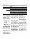
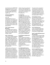
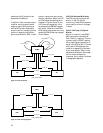
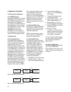
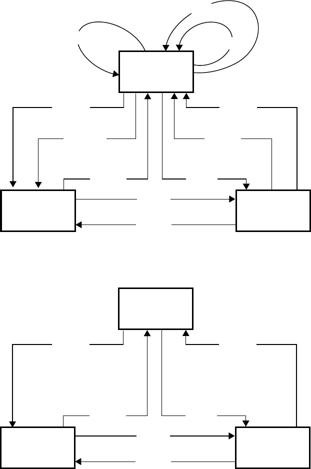
Figure 15. Pointer Processing
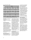
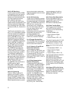
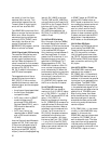
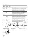
Figure 16. Pointer tracking algorithm
pointer, new pointer and concat-
enation indication. When the LOP
or LOPC states are entered as in-
dicated in Figures 15 and 16, the
LOP interrupt request bit in the
corresponding OR#IRQ2 register
will be set. Likewise if the AIS or
AISC states are entered, the corre-
sponding HPAIS interrupt request
bit will be set.
3.9.4.9 Path Overhead Monitoring
The POH monitoring block con-
sists of J1, B3, C2, and G1
monitoring. These POH bytes are
monitored for errors or changes
in state.
3.9.4.9.1 Path Trace (J1) Capture/
Monitor
As with J1 insertion, the HDMP-
3001 supports two methods of
Path Trace (J1) capture. The first,
typically used in SONET applica-
tions, captures 64 consecutive J1
bytes in the STS-3c/AU-4. The sec-
ond, used in SDH applications,
looks for a repeating 16 consecu-
tive J1 byte pattern. When it has
detected a consistent 16 byte pat-
tern for three consecutive
instances, the J1 pattern is stored
in designated registers.
LOP
NORM
Nx inv_point
3x AIS_ind
3x AIS_ind
AIS
NDF_enable
NDF_enable
Nx NDF_enable
3x norm_point
Nx inv_point
NOTE: x MEANS TIMES
3x norm_point
3x norm_point
lnc_lnd/dec_lnd