


38
4. Application Information
4.1 Chip setup and configuration
4.1.1 EEPROM Detection
After reset, HDMP-3001 will probe
the SDA pin. If tied to ground, no
boot EEPROM is present and nor-
mal operation will resume. If
connected to an EEPROM, SDA is
pulled high by an internal resistor
and HDMP-3001 will start to load
its configuration from the
EEPROM. During this time,
HDMP-3001 will not respond to
any transactions on the micropro-
cessor or MII Management ports.
4.2 Configurations
4.2.1 PHY and MAC mode
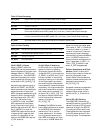
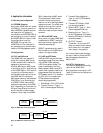
The HDMP-3001 can operate in
either PHY mode or MAC mode.
In PHY mode the MII interface is
designed to connect to an
Ethernet MAC and in MAC mode
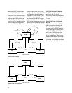
to connect to a PHY. A typical use
of the HDMP-3001 in PHY mode is
in a port of an Ethernet switch.
Here the MII clocks are driven by
the HDMP-3001. Examples of
MAC mode use are in a standalone
DSU/CSU or in an Ethernet port
of a SONET ADM. Here the MII
clocks are received by the HDMP-
3001. Depending on the mode, the
MII pins have different functions
and the two MII clocks change
direction. After reset, the HDMP-
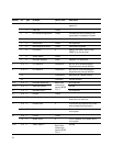
HDMP-3001
(MAC MODE)
HDMP-3001
(MAC MODE)
PHY
SONET
MII_TCLK
MII_RCLK
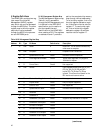
HDMP-3001
(PHY MODE)
HDMP-3001
(PHY MODE)
SWITCH WITH
INTEGRATED MACs
SONET
MII_TCLK
MII_RCLK
Figure 18. HDMP-3001 connecting to a MAC
Figure 19. HDMP-3001 connecting to a PHY
3001 is defaulted to MAC mode.
This is because in MAC mode
both MII clocks are inputs so
there is no risk of having enabled
opposing drivers. The mode is se-
lected by writing to an internal
register which should only be
done after reset and then remain
constant.
4.2.2 SDH and SONET mode
After power on reset, HDMP-3001
is defaulted to SONET mode. By
setting an internal register, SDH
mode can be selected.
SONET is predominantly used in
North America, while SDH domi-
nates in Europe and Asia.
4.2.3 LAPS and GFP mode
LAPS and GFP are two different
standards to map Ethernet frames
into a SONET/SDH payload.
LAPS is the default mode. The
mode is selected by the Chip
Mode register. When using GFP
mode, other registers need to be
programmed to set the desired
GFP header option. For instance,
for GFP with null headers and
FCS enabled these registers
should be programmed:
1. Chip Mode = 0x01 (GFP mode)
2. Transmit Control / Type_L =
0x01 (frame-mapped Ethernet)
3. Transmit Rate Adaptation /
Type_H = 0x10 (FCS enabled,
null header)
4. Transmit GFP Mode = 0x04
(no extended header)
5. Receive ADR / Type_L = 0x01
(frame-mapped Ethernet)
6. Receive Control / Type_H =
0x10 (FCS enabled, null header)
7. Receive GFP Mode = 0xA0 (no
extended header)
8. RX-FIFO Transmit
Threshold = 0x14, since GFP
does not need to buffer data to
avoid underrun in the case of
many flags in the payload
For further details, see the regis-
ter map in Section 5 and the GFP
data processing discussion in
Section 3.8.2.
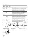
4.2.4 INT Pin Configuration
This section specifies the configu-
ration of the HDMP-3001
Microprocessor Interrupt pin INT.
Table 15 shows the configurations
of the pin.