


English 9
2 NAMES AND FUNCTIONS OF PARTS
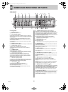
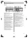
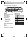
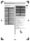
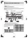
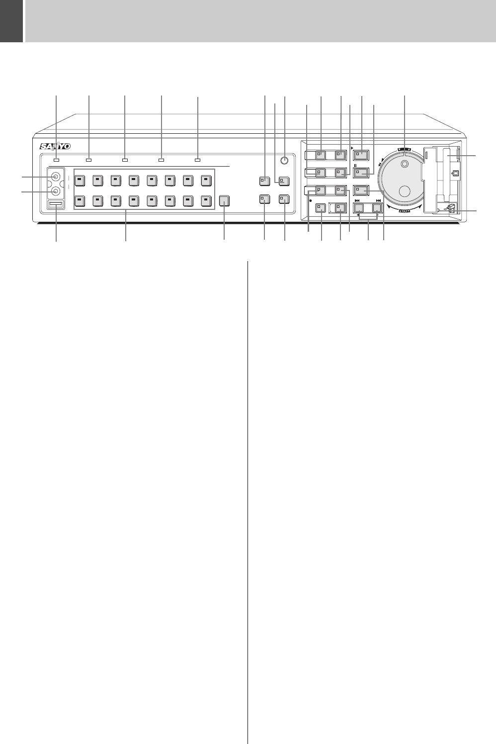
Front panel
1. POWER indicator
Lights up when the power is on.
2. FULL indicator (JP.81)
Flashes when the amount of available memory in the hard
disk’s recording area drops to the percentage specified using
menu settings.
In addition, recording stops automatically when no more
memory is available, and the FULL indicator switches to a
permanently lit condition.
The indicator can then be turned off by performing “AREA
FULL RESET”.
3. ERROR indicator (JP.17)
This indicator flashes if the HDD or fan begins to malfunction.
4. LOCK indicator (JP.113)
Lights up when operations have been locked.
The LOCK indicator turns off when the lock condition is
cancelled.
5. ALARM indicator
Flashes during alarm recording.
The ALARM indicator lights up during pre-alarm recording.
6. AUDIO OUT (RCA) terminal
Connect this terminal and VIDEO OUT terminal to a
commercially-available VCR or DVD recorder to enable
copying of recorded audio and video. (Same as the audio
output terminal on the rear panel)
7. VIDEO OUT (RCA) terminal
Connects to a commercially-available VCR or DVD recorder
to enable copying of recorded video. (Same as the MAIN
MONITOR output terminal on the rear panel)
8. USB terminal (JP.54)
Connects to a recordable CD or DVD drive.
For compatibility, refer to the SANYO homepage.
http://www.sanyosecurity.com/
The rear panel and front panel USB terminals cannot be
connected to simultaneously.
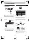
9. [CAMERA SELECT] buttons and indicators
When one or more cameras have been connected to the
VIDEO IN terminals on the digital video recorder’s rear panel
and the appropriate [CAMERA SELECT] button is pressed,
the corresponding indicator lights up and the video feed from
that camera is displayed on-screen.
z During quad, multi 9, or multi 16 screen display:
The indicators corresponding to the cameras being
displayed on the monitor light up.
z During video loss:
The indicator starts to flash.
z If an alarm occurs:
The indicator for the corresponding camera starts to flash.
10. [AUDIO] button
Audio input channels connected to the rear panel AUDIO IN
terminal can be switched.
Each time this button is pressed, the channel changes in the
following order: 1+2, OFF, 1, 2.
11. [FUNC.] button
Activates dome camera operation mode. The operation of
other buttons changes. (JP.145) Use also for advanced
menu functions.
12. [QUAD] button and indicator (JP.23)
Displays video in quad screens. The indicator lights up while
in quad screen display.
The indicator turns off when using a different screen display
mode.
13. [MULTI] button and indicator (JP.24)
Displays video in multi 9 or multi 16 screen display.
The indicator lights up while in multi 9 or multi 16 screen
display.
The indicator turns off when using a different screen display
mode.
The DSR-5009P can only display video in nine screens.
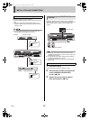
14. [MON2] button and indicator (JP.26)
If the [MON2] button is pressed while a monitor is connected
to the MON2 output terminal on the rear panel, it is possible to
change the monitor 2 video. The [CAMERA SELECT],
[SEQUENCE], [QUAD], [MULTI] and [PLUS] buttons can be
used. The indicator lights up when this mode is selected.
15. [PLUS] button (JP.24)
Changes the video from a single camera to quad screen size
during multi 9, multi 16, full screen or quad screen display.
For DSR-5009P, this operation is available when in multi 9,
quad and full screen display.
SEARCH
678123
45
14 15
1691011
12 13
MENU
MENU
EXIT/OSD
ZOOM
SEQUENCE
COPY
SHUTTLE HOLD
TIMER
ALARM
PLAY/STOP
ENTER AF
IRIS
FOCUS
STILL
REC/STOP
POWER FULL ERROR LOCK ALARM
AUDIO
MULTI
FUNC.
TOUR
SEQUENCE
AUTO PAN
AUDIO
VIDEO
OUT
USB
PLUSMON 2
QUAD
PRESET
JOG
SHUTTLE
C
L
E
A
R
E
N
T
E
R
PAN
ZOOM/I/FO
CARDCARD
MENU
RESET
EJECT
1 2 3 4 5
9
12 11
14 15
16 17 18
2019 21
28
22
25
26 27 24
23
29
30
6
7
8 10
13
DSR-5016P
e00_l8hbd_xe_7.book Page 9 Tuesday, April 5, 2005 11:41 AM