NAMES AND FUNCTIONS OF PARTS2
English 11
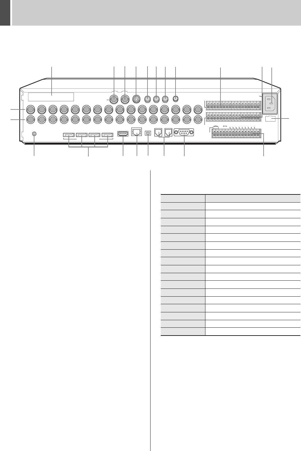
Rear panel
1. SCSI terminal (option board)
Used to add a RAID unit by SCSI connection. Cannot be used
together with an expansion unit. Only a RAID unit can be
used.
Please contact the dealer for details.
When handling and connecting, be sure to read the instruction
manual included with the option board.
2. VIDEO IN terminals
Connects to video cameras.
The DSR-5009P has nine terminals.
3. VIDEO OUT terminals
Connects to a monitor to view camera images.
The DSR-5009P has nine terminals.
4. MAIN MONITOR output terminal
Connects to the main monitor.
5. MON2 output terminal (digital output)
Connects to monitor 2.
6. S-VIDEO output terminal
Connects to a high-quality device.
The same image is output to the main monitor.
7. AUDIO1 IN terminal
Used to connect to an audio amplifier. A microphone or
wireless device can then be connected to the amplifier. Use
with AUDIO2 IN terminal to record and play back audio from
two locations.
8. AUDIO2 IN terminal
Connects to an audio amplifier in the same manner as
AUDIO1 IN terminal.
9. AUDIO OUT terminal
10. MIC IN terminal
Connects to a microphone.
The MIC IN terminal is given priority over the AUDIO1/2 IN
terminal.
11. ALARM IN terminals (1 to 16)
Connects to an externally installed alarm switch. Operate the
alarm switch for alarm recording.
The DSR-5009P has nine terminals.
EXTERNAL STRAGE UNIT
MONITOR OUT
SCSI
MAIN
USB
LAN
TERMINATE
RS-485
OFF ON
MON2 S-VIDEO 1-AUDIO-2
AUDIO OUT
A SANYO SSP B
RS-232C
RS-485
ALARM IN
AC IN
SENSOR
ALARM OUT
DO NOT CONNECT TO PHONE LINE
MIC IN
A
2ND
RS-485/422
CLOCK IN
C
LOCK
OUT
EXT TIMER IN
ALARM
OUT
ALARM RESET
NO
N RE
C O
UT
WARNING OUT
FULL
ARCHIVE FULL
REMOTE
EXCEPT SANYO SSP
CONTROL
BC
C
123456789
10 11 12 13 14 15 16
C
R1 R2
1
1234
IN
OUT
ALL
RESET
2 3 4 5 6 7 8 9 10 11 12 13 14 15 16
IN
11
12
21
13181514
2
3
19
1
4
5 6 7 8 9 10
16
17
20
22
DSR-5016P
The number of terminals for the DSR-5009P may differ. For more details, see below.
Pin Signal
C Ground
ALARM IN 1 Alarm input No. 1
ALARM IN 2 Alarm input No. 2
ALARM IN 3 Alarm input No. 3
ALARM IN 4 Alarm input No. 4
ALARM IN 5 Alarm input No. 5
ALARM IN 6 Alarm input No. 6
ALARM IN 7 Alarm input No. 7
ALARM IN 8 Alarm input No. 8
ALARM IN 9 Alarm input No. 9
ALARM IN 10 Alarm input No. 10
ALARM IN 11 Alarm input No. 11
ALARM IN 12 Alarm input No. 12
ALARM IN 13 Alarm input No. 13
ALARM IN 14 Alarm input No. 14
ALARM IN 15 Alarm input No. 15
ALARM IN 16 Alarm input No. 16
e00_l8hbd_xe_7.book Page 11 Tuesday, April 5, 2005 11:41 AM


