INSTALLATION AND CONNECTIONS3
English 17
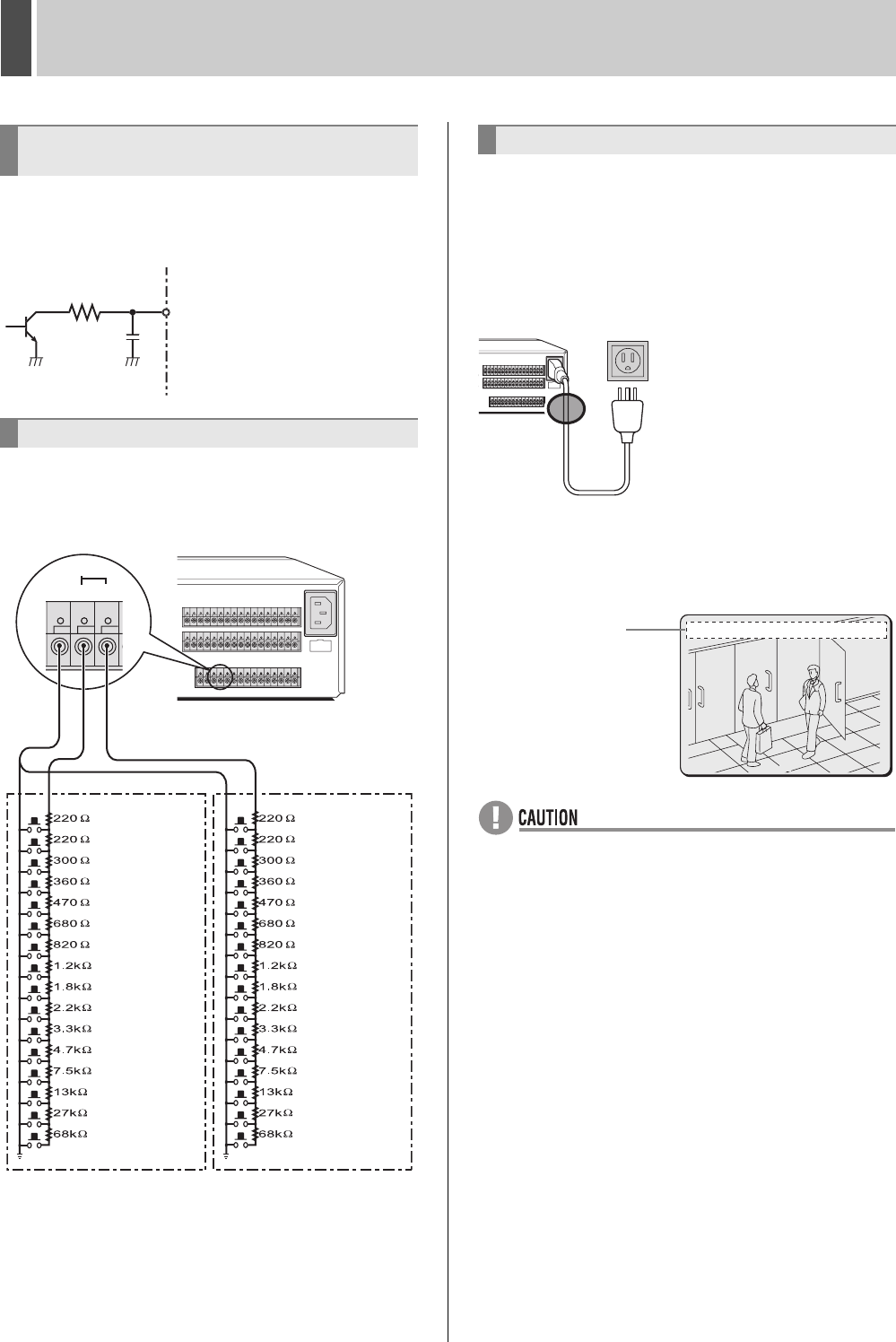
The SENSOR ALARM OUT terminals are used to relay alarm
signals whenever one of the digital video recorder’s motion
sensors is triggered. Normally in an open condition, a terminal
adopts a low condition when a sensor for the corresponding
camera number has been triggered.
The connections for a remote control circuit are shown below.
This digital video recorder can be remotely controlled when a
remote-control circuit similar to that shown here is connected
to the remote-input control terminals.
z Use a resistance of 1/10 ohms or more and with a D
ranking (Precision within ±0.5%).
z The remote control cable should be no more than 5 m long.
* The DSR-5009P can operate up to nine cameras.
1 After all other connections are made,
make sure the voltage is 120 V-240 V AC
and then insert the power plug into the
wall outlet.
There is no power switch. The display indicators flash, and
after a few moments, the monitor screen displays the camera
video.
z When turning the power on for the first time
“PLEASE SET THE CLOCK” is displayed on the monitor
screen. Set the clock. (JP.20)
z If the clock is already set
The operation display area is displayed.
z If the ERROR indicator starts flashing
The digital video recorder has a self-diagnostic function to
find malfunctions. If a malfunction occurs while the power
is on, the ERROR indicator flashes in a cycle to indicate
the malfunction.
If the ERROR indicator flashes, contact a Sanyo service
center.
When flashing at 4Hz (Four times per second):
The hard disk is checked automatically when the power is
turned on. The POWER indicator flashing indicates that a
malfunction has been found on the hard disk and the hard
disk must be replaced or initialized. If you need to save
video stored on the disk, contact a Sanyo service center.
When flashing at 1Hz (Once per second):
A fan malfunction has occurred.
z The power cord’s ground terminal is not provided for
enhanced safety; rather, it is used to reduce the level of
interference when the digital video recorder is connected to
analog devices.
If a large amount of noise is generated when the digital
video recorder is connected to analog devices, connect
this terminal to the building earth ground.
Connecting SENSOR ALARM OUT
terminals
Connecting control terminals
1
K
Rated value of terminals
z Maximum current: 25 mA
z Maximum voltage: 25 V
REMOTE
CR1R2
SW 1
SW 2
SW 3
SW 4
SW 5
SW 6
SW 7
SW 8
SW 9
SW 10
SW 11
SW 12
SW 13
SW 14
SW 15
SW 16
SW 17
SW 18
SW 19
SW 20
SW 21
SW 22
SW 23
SW 24
SW 25
SW 26
SW 27
SW 28
SW 29
SW 30
SW 31
SW 32
R1 R2
:
Camera 1:
INDEX+
:
Camera 2
:INDEX-
:
Camera 3
:AUTO FOCUS
:Camera 4 :Automatic selection display
:
Camera 5:
Monitor2
:
Camera 6:
Plus display
:
Camera 7
:QUAD
:
Camera 8
:MULTI
:
Camera 9
:MENU RESET
:
Camera 10
:
Not used
:
Camera 11
:
PAN left
:
Camera 12
:
PAN right
:
Camera 13
:
TILT down
:
Camera 14
:
TILT up
:
Camera 15
:ZOOM wide
:
Camera 16
:
ZOOM tele
:REC/STOP
:PLAY/STOP
:STILL
:SEARCH
:
SHIFT (Doubles with R1)
:PLAY
:REC
:MENU
:MENU EXIT(EXIT)
: +
: -
: +
: -
:ZOOM
:COPY
:TIMER
(When operated
independently)
(When combined
with R2 FUNC key)
Connecting the power cord
120 V-240 V AC
(50/60 Hz)
* Attach the core clamp
(large) to the power cord.
*
02
0
01-01-05 00:00:00 EN A
Operation
display area
e00_l8hbd_xe_7.book Page 17 Tuesday, April 5, 2005 11:41 AM


