


12 English
NAMES AND FUNCTIONS OF PARTS2
INTRODUCTION SETTINGS NETWORK
CONTROL
NETWORK
OPERATION
NETWORK
SETTINGS
OTHEROPERATION
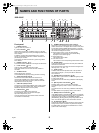
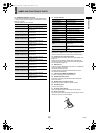
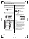
12. SENSOR ALARM OUT terminals
The terminals are used when motion sensors have been set
(JP.99) to output an alarm signal to a connected device upon
detection of motion.
The DSR-5009P has nine terminals.
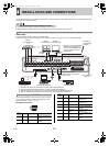
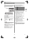
13. Control terminals
14. [ALL RESET] button
When the [ALL RESET] button is pressed, the digital video
recorder is reset and the time is returned to its default setting.
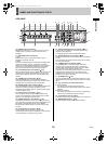
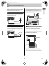
15. Expansion unit connection terminal
Used to expand the hard disk. Cannot be used together with
RAID unit.
Please contact the dealer for details. When handling and
connecting, be sure to read the instruction manual included
wtih the external storage unit.
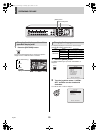
16. USB terminal
Connects to a recordable CD or DVD drive. For compatibility,
refer to the SANYO homepage.
http://www.sanyosecurity.com/
The rear panel and front panel USB terminals cannot be
connected to simultaneously.
17. LAN terminal (10BASE-T/100BASE-TX)
Connect to switching hubs, routers and PCs.
18. RS-485 termination switch
Used when connecting multiple devices from the RS-485
control connectors.
19. RS-485 control connectors (A) (B)
Connects to a system controller or dome cameras.
20. RS-232C terminal
Connects to a modem.
21. AC power socket (AC IN)
Insert the supplied power cord securely into this socket.
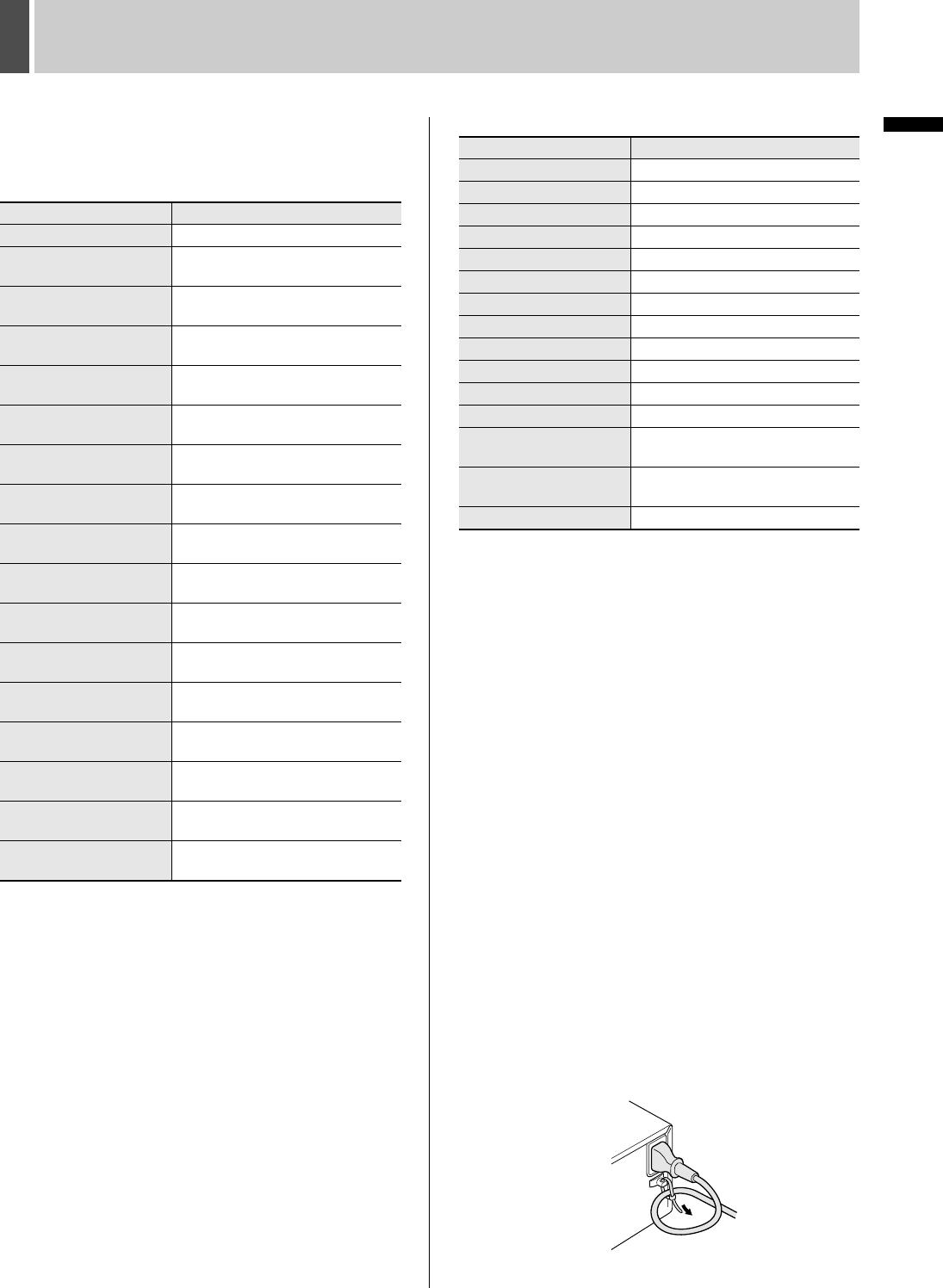
22. Power cord holder
Secure the power card to the holder using the power cord tie
(accessory) as shown in the illustration.
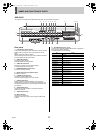
Pin Signal
C Ground
SENSOR ALARM OUT 1
Output of an alarm signal for
Camera No. 1
SENSOR ALARM OUT 2
Output of an alarm signal for
Camera No. 2
SENSOR ALARM OUT 3
Output of an alarm signal for
Camera No. 3
SENSOR ALARM OUT 4
Output of an alarm signal for
Camera No. 4
SENSOR ALARM OUT 5
Output of an alarm signal for
Camera No. 5
SENSOR ALARM OUT 6
Output of an alarm signal for
Camera No. 6
SENSOR ALARM OUT 7
Output of an alarm signal for
Camera No. 7
SENSOR ALARM OUT 8
Output of an alarm signal for
Camera No. 8
SENSOR ALARM OUT 9
Output of an alarm signal for
Camera No. 9
SENSOR ALARM OUT 10
Output of an alarm signal for
Camera No. 10
SENSOR ALARM OUT 11
Output of an alarm signal for
Camera No. 11
SENSOR ALARM OUT 12
Output of an alarm signal for
Camera No. 12
SENSOR ALARM OUT 13
Output of an alarm signal for
Camera No. 13
SENSOR ALARM OUT 14
Output of an alarm signal for
Camera No. 14
SENSOR ALARM OUT 15
Output of an alarm signal for
Camera No. 15
SENSOR ALARM OUT 16
Output of an alarm signal for
Camera No. 16
Pin Signal
2ND RS485/422 A Control terminal (A)
2ND RS485/422 B Control terminal (B)
C Ground
REMOTE R1 Remote input 1
REMOTE R2 Remote input 2
CLOCK IN Clock adjust input terminal
CLOCK OUT Clock adjust output terminal
EXT TIMER IN External timer input terminal
ALARM OUT Alarm output terminal
ALARM RESET Cancels alarm
NON REC OUT Non-recording output
WARNING OUT HDD or FAN error warning output
FULL
Capacity warning output for
recording area
ARCHIVE FULL
Capacity warning output for archive
area
C Ground
e00_l8hbd_xe_7.book Page 12 Tuesday, April 5, 2005 11:41 AM