TECHNICAL SPECIFICATIONS
Connectors and Pinouts
350-9047 v3.0.1 DGy Model 201x User’s Guide 129
. . . . .
CROSSOVER CABLES
To connect directly from a PC (such as a laptop) to the DGy 201x
without connecting to the network, an Ethernet crossover cable must be
used. Crossover cables are available commercially.
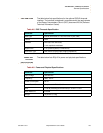
In a crossover cable, one end of the cable is wired as a straight through
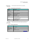
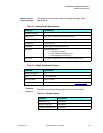
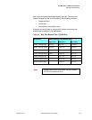
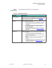
cable, using the pin assignments shown in
Table A-11. At the other end
of the cable, the TX and RX interconnections are exchanged (crossed
over).
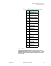
Ethernet uses balanced differential signals on twisted pairs of
conductors. It is important to use wires from the same pair for each pair
of signals. The standard pairs are shown in
Table A-11. Note that one
wire of the pair has a solid color. The other wire (of the pair) is white with
a stripe of the same color as the other wire (e.g., Orange and
White/Orange).
. . . . . . . . .
RS-232 CONNECTOR
The RS-232 port is configured according to the Electronic Industries
Association Standard RS-232-C published in August 1969. The DGy
201x can be explicitly controlled with ASCII Command Set instructions
sent via the RS-232 serial port from either a computer or an ASCII
terminal. Refer to
Chapter 6, for details on all commands.
CONNECTOR TYPE AND PINOUTS
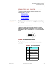
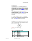
Physically, the RS-232 port is a 9-pin, D-Sub female connector. The pins
for the RS-232 connector are numbered from top to bottom, right to left.
Looking at the connector, pin #1 is located in the upper right corner, and
pin #9 is in the lower left corner.
Figure A-3 RS-232 Female Connector
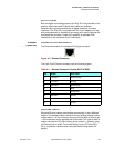
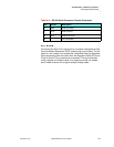
The 9-pin D-Sub connector has the following signals:
Table A-12 RS-232 Serial Connector Pinouts
Pin Circuit Description
1 CD Carrier Detect
2 TD Transmit Data
3 RD Received Data
4 (not connected)
5 AB Signal Ground (common return)


