INSTALLATION AND SET UP
Rear Panel
350-9047 v3.0.1 DGy Model 201x User’s Guide 16
. . . . .
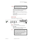
3) Graphics Loop
Use the Graphics Loop connector to pass the unprocessed
input signal to an external device such as a monitor. This
connector provides looping for both the digital (DVI) and analog
RGB signals. This is an active loop, so there will be no output
when the DGy 201x has no power applied.
4) Graphics Output
This Graphics Output connector provides both analog RGB
and digital DVI output signals on a DVI-I connector. When the
DGy 201x is in Play mode, the output signal plays back from
recorded material on a disk. When DGy 201x is in Record
mode, the output signal displays the signal present at the
Graphics Input connector.
A DGy equipped with the simultaneous record/play option will
display the playback on the Graphics Output connector
whenever the DGy is in Play mode even when the unit is
recording.
5) Audio Inputs
The DGy 201x provides stereo recording capability. A pair of
RCA phono Audio Input connectors accept analog audio
signals for left and right channels. The Audio Input will accept
either line or microphone level inputs. A choice of sample rates
is provided.
6) Audio Outputs
A pair of RCA phono Audio Output connectors supply the line
level left and right analog audio output signals.
7) Ethernet Port
A standard RJ-45 connector is provided for the Ethernet
100/1000 Base-T control port. This port is used to control the
DGy 201x with the RGB Spectrum graphical interface (Web
Control Panel), Telnet command line interface, or for the transfer
of recorded clips over a network (using FTP).
8) RS-232 Port
A standard 9-pin sub-miniature D connector provides serial
connection to an external RS-232 equipped control device. The
serial port does not support a graphical user interface.
9) IRIG Ports (option)
The optional IRIG timecode input accepts IRIG-B timecode in
either DCLS or 1kHz modulated formats (B123 format). The
looping output can be used to provide a reference signal to
other IRIG-B compatible devices.
Note The GPIO connector is non-operational at this time.


