


A-6 Appendix
Appendix
Warning Messages
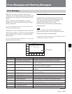
Error Messages and Warning Messages
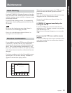
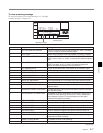
When one of the problems described below is detected,
a warning mark is displayed in the upper left corner of
the display. Operation can continue even when the
mark is flashing.
If you press the SFT button (see page 2-6) and the
DIAG button (see page 2-5) when the mark is flashing,
an information display appears, showing a warning
message.
Note
The warning messages can be viewed in any menu
except the CUE or SET UP menu.
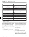
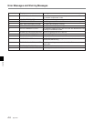
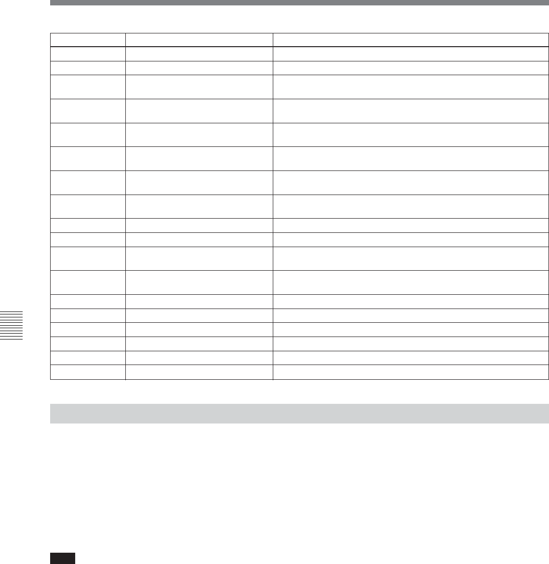
Item number Display Meaning
13 TAPE END ERROR A tape end sensor fault was detected.
14 FAN MOTOR ERROR A cooling fan motor operation fault was detected.
20 CC TIME OVER A fault was detected in a cassette compartment raising or lowering
operation.
21 SHIFT TIME OVER A fault was detected movement of the reel table to adjust for cassette
size.
22 POSITION BOTH DETECT The reel table was detected in the L cassette position and S cassette
position at the same time.
23 THREAD BOTH DETECT The threading end and unthreading end were detected at the same
time.
93 DR IF ERROR A communications error between the servo CPU (board SS-95) and
drum CPU (board DR-508) was detected.
97 NVRAM CHECK SUM ERROR An operation fault was detected in the servo system NV-RAM (board
DR-508).
FF SV UNDEFINE ERROR Undefined SV error was detected.
A0 SY UNDEFINE ERROR Undefined SY error was detected.
A2 SY1-SY2 DPRAM ERROR A DPRAM (board SS-95) operation fault between SYS1 and SYS2
was detected.
A5 SY-FC DPRAM ERROR A DPRAM (board FC-91) operation fault between SYS1 and FC was
detected.
A8 SY NVRAM CHECK SUM ERROR A SYS NVRAM (board SS-95) operation fault was detected.
B8 SY1-SY2 INTERFACE ERROR A SYS CPU communications fault was detected.
B9 SY-SV INTERFACE ERROR An SV CPU communications fault was detected.
BA SY-EQ INTERFACE ERROR An EQ CPU communications fault was detected.
BB SY-FC INTERFACE ERROR An FC CPU communications fault was detected.
BC SY-50PIN INTERFACE ERROR A communications fault with the 50-pin CPU was detected.
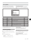
Only one message will be displayed even if there are
multiple messages. The number of errors appears at
the lower right, and you can check the messages using
the R and r buttons.
A history of errors is kept in the error log menu.
For more information about warning messages, refer to the
Maintenance Manual Volume 1.
Use the displayed warning information to eliminate the
cause of the warning.
For more information about eliminating the cause of
warning, refer to the Maintenance Manual Volume 1.
To automatically display a warning message
Whenever a warning occurs, change the setting of the
VTR SETUP menu item 120 “WARNING DISPLAY”
to “on”.