


Chapter 2 Locations and Functions of Parts 2-5
Chapter 2 Locations and Functions of Parts
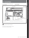
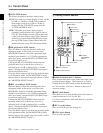
4 Menu selection buttons
These select the menu screen displayed on the display.
HOME button: Press this to go to the HOME menu
screen. The home menu provides settings for the
basic VTR operations and editing operations.
TC button: Press this to go to the TC (time code)
menu screen. In the time code menu, you can
switch LTC/VITC, switch DF/NDF, set the time
code to be displayed on an external monitor, and
so on.
VIDEO button: Press this to go to the VIDEO menu
screen. Use it to make video related settings.
AUDIO button: Press this to go to the AUDIO menu
screen. Use it to make audio related settings.
CUE button: Press this to go to the CUE menu
screen. The cue menu provides 10 pages to set cue
points. You can set up to 10 cue points per page.
You can also make settings for the Tele-File
memory label system.
PF1 button: Press this to go to the PF1 (personal
function 1) menu screen. You can register
frequently-used items in the PF1 menu. The
factory default setting is blank.
PF2 button: Press this to go to the PF2 (personal
function 2) menu screen. You can register
frequently-used items in the PF2 menu. The
factory default setting is blank.
SET UP button: Press this to go to the SET UP
menu screen. The setup menu provides functions
to save menu settings in VTR banks or save to a
memory stick, registration operations in the PF
buttons, VTR SETUP menu settings, and so on.
For details of menus, see “Chapter 4 Menu Settings” (page
4-1).
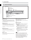
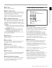
5 Color display
This comprises principally the audio level display and
menu display.
Audio Level display:
In recording mode or E-E mode
1)
, this displays the
audio recording levels.
In playback mode or CONFI mode, this displays the
playback levels.
The display mode can be changed with the FULL/
FINE button. The factory default display is a reference
level of –20 dB, and peak level 0 dB.
Menu display:
This displays the menu screen selected by the menu
selection buttons.
Each menu screen shows the functions assigned to the
function buttons ([F1] to [F10]), and shows
simultaneously information required for time code
display settings and so on.
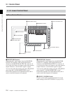
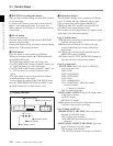
6 Function buttons
Activates the functions in each menu.
7 ALT (alternative) button
Press to change the items displayed on the current
menu. Press again to return to the original items.
8 DIAG (diagnostic) button
Hold down the SFT button (see page 2-6) in the
editing control section and press this switch to switch
to the DIAG menu.
9 DISPLAY button
This displays the down-converted output signal in the
whole color display.
Notes
•Depending on the system settings, it may not be
possible to output some signals.
• This function is for a quick check of the output
signal, and cannot be used as a monitor.
1) E-E mode
An abbreviation for Electric-to-Electric mode. In this
mode, video or audio input signals are passed and output
..........................................................................................................................................................................................................
only through the VTR’s internal circuitry, and not
through the magnetic conversion system comprising tape
and heads.