


Chapter 2 Locations and Functions of Parts 2-13
Chapter 2 Locations and Functions of Parts
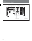
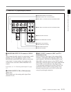
1 ANALOG I/O (input/output) section
1 MONITOR OUTPUT L/R connectors (XLR-3-
31)
These output the audio signals for monitoring L and R
channels. To select the signals to output, use the
MONITOR R and MONITOR L buttons on the lower
control panel. A menu setting can be made so that
volume can be controlled with the PHONES level
control.
For details, see “5-1-2 Selecting Audio Signals”on page
5-2.
2 AUDIO OUTPUT CH1 to CH4 connectors
(XLR-3-31)
These output up to four analog audio signal lines
(channels 1 to 4).
AUDIO OUTPUT
MONITOR OUTPUT
CUE
TIME CODE
ANALOG I/O
HD REF OUT SD OUT
CH1
RLINOUT
1
OFF ON
75Ω 75Ω
2 (OPTION)
OFF ON
OUT
1
2
SYNC
COMPOSITE
(MONITOR)
CH2 CH3 CH4
REF INPUT
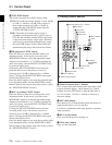
1 MONITOR OUTPUT L/R connectors
2 AUDIO OUTPUT CH1 to CH4 connectors
4 REF. INPUT 2 connectors and 75 Ω termination switch
5 SD OUT SYNC connector
3 REF. INPUT 1 connectors and 75 Ω termination switch
6 SD OUT COMPOSITE connector
7 HD REF. OUT connectors
8 TIME CODE OUT connector
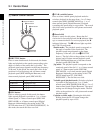
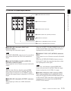
3 REF. INPUT 1 connectors (BNC) and 75 Ω
termination switch
Input a reference video signal of the selected field
frequency. Select HD or SD with the VTR SETUP
menu item 006 “EXTERNAL REFERENCE select”.
When HD is selected, input a tri-level SYNC signal.
When SD is selected, input a video signal with chroma
burst (VBS) or a monochrome video signal (VS).
A loop-through connection is possible. Set the 75 Ω
termination switch to OFF if you are using a loop-
through connection and set it to ON if you are not
using a loop-through connection.
9 TIME CODE IN connector
0 CUE OUT connector