


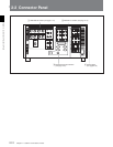
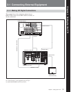
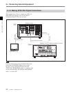
2-2 Connector Panel
2-14 Chapter 2 Locations and Functions of Parts
Chapter 2 Locations and Functions of Parts
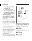
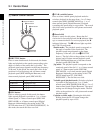
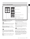
4 REF. INPUT 2 connectors (BNC) and 75 Ω
termination switch
Input a reference video signal of the field frequency
selected for the format converter output. Select HD or
SD with the VTR SETUP menu item 006
“EXTERNAL REFERENCE select”. When HD is
selected, input a tri-level SYNC signal for external
synchronization. When SD is selected, input a video
signal with chroma burst (VBS) or a monochrome
video signal (VS). A loop-through connection is
possible. Set the 75 Ω termination switch to OFF if
you are using a loop-through connection and set it to
ON if you are not using a loop-through connection.
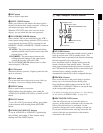
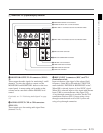
5 SD OUT SYNC connector (BNC)
This outputs an NTSC or PAL signal for external
synchronization.
Note
The output phase is the same as that of the composite
signal output from the SD OUT COMPOSITE
connector.
Because the output phase changes with the operation
mode of the VTR, use this for synchronization with the
video monitor.
6
SD OUT COMPOSITE connector (BNC)
Outputs an analog composite signal for a video
monitor. When the ALT/[F6] (CHARA SUPER)
setting in the TC menu is on, character signals such as
time codes are superimposed on the output.
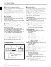
7 HD REF. OUT connectors (BNC)
Output an HD tri-level sync signal during tape
playback.
8 TIME CODE OUT connector (XLR-3-31,
female)
Outputs the following time codes according to the
VTR operation mode.
In playback mode: Playback time code
In recording mode: Time code generated by the
internal time code generator, or time code input to
the TIME CODE IN connector.
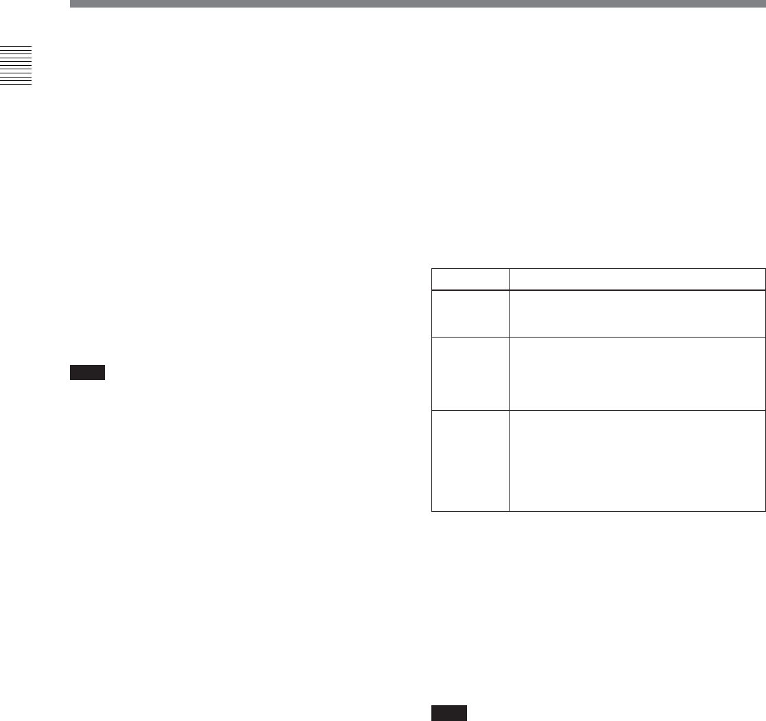
To select the output signal, use the VTR SETUP menu
item 613 “TC OUTPUT SIGNAL IN REGEN
MODE.”
9 TIME CODE IN connector (XLR-3-32, male)
Accepts external time code for recording to tape.
Connect to the time code output connector of the
external equipment.
0 CUE OUT (cue output) connector (XLR-3-31,
female)
Outputs cue track audio during HDCAM or Digital
Betacam playback.
Note
There is no cue track on an HDCAM-SR tape, and
therefore no output.
Setting Description
off tape In playback mode, playback time code signal
is output. In recording mode, TCG time code
signal is output.
regene Only when the servo is locked in playback
mode, playback time code signal is
regenerated and output. In all other cases,
output is the same as for the "off tape"
setting.
through
The time code signal from the TIME CODE
IN connector is output as is. (Used for
cascade connections.)
(For more information about cascade
connections, see 3-1-3 “Cascade
Connection” on page 3-3.)