


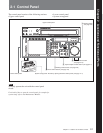
2-1 Control Panel
2-6 Chapter 2 Locations and Functions of Parts
Chapter 2 Locations and Functions of Parts
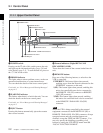
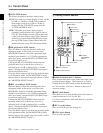
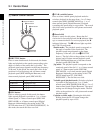
0 FULL/FINE button
This selects the audio level meter display range.
FULL: The audio level meter display is from –60 dB
to 0 dB, or –40 dB to +20 dB. Select which of
these ranges (peak level: 0 dB or +20 dB) is
displayed in the VTR SETUP menu item 814
“LEVEL METER SCALE”.
FINE: The audio level meter display range is
expanded, and displayed with a scale in steps of
0.25 dB. The reference marker LED at the center
of the level meter display range lights. When the
audio level exceeds the maximum display range,
the top OVER display flashes. When under the
minimum display range, the bottom line flashes.
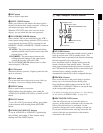
qa PB (playback) LEVEL button
Press this button to enter the playback audio level
adjustment mode. In this mode, you can use the
MONITOR R button to select the adjustment target
channels from channels 1 to 12. While watching the
audio level meter, turn the MULTI CONTROL knob
for a desired audio level.
Clicking the MULTI CONTROL knob resets the
playback audio level to the factory set level (a
reference level of 0 dB is displayed for a +4 dBm
input). Clicking the MULTI CONTROL knob again
restores the adjusted level.
Press this button again to exit from the playback audio
level adjustment mode, and the MONITOR L and R
buttons return to the normal status (this status is called
the “MONITOR SELECT mode”).
qs REC (recording) LEVEL button
Press this button to enter the recording audio level
adjustment mode. In this mode, you can use the
MONITOR L button to select the adjustment target
channels from channels 1 to 12. While watching the
audio level meter, turn the MULTI CONTROL knob
for a desired audio level.
Clicking the MULTI CONTROL knob resets the
recording audio level to the factory set level (a
reference level of 0 dB is displayed for a +4 dBm
input). Clicking the MULTI CONTROL knob again
restores the adjusted level.
Press this button again to exit from the recording audio
level adjustment mode, and the MONITOR L and R
buttons return to the normal status (this status is called
the “MONITOR SELECT mode”).
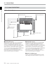
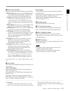
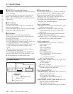
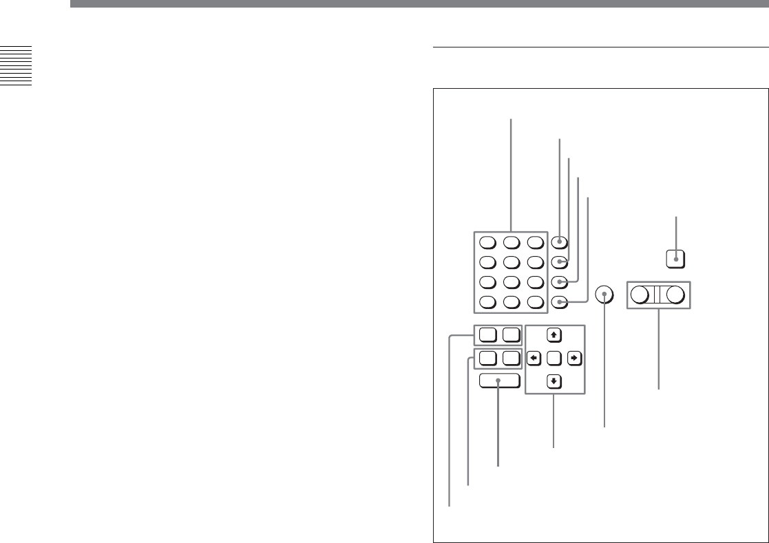
2 Editing Control Section
1 Numeric buttons and +/– buttons
Press to input time data or edit points data at the cursor
position in menu display. Press buttons 0 to 5 while
holding down the SFT button to input hexadecimal A
to F for user bits. Use the +/– buttons to increase or
decrease settings.
2 SFT (shift) button
Press buttons 0 to 5 while holding down this button to
input hexadecimal A to F for user bits.
Use also in combination with other buttons to perform
other operations.
3 RCL (recall) button
Press to recall the previous setting, etc.
4 CLR (clear) button
Press to clear input data.
7
8
9
SFT
4
5
6
RCL
1
2
3
CLR
0
E
F
B
C
D
AUTO
AUDIO
VIDEO
PLAYER RECORDER
INPUT
CHECK
A
+
–
SET
IN OUT
ENTRY
IN OUT
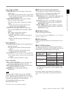
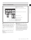
1 Numeric buttons and +/– buttons
2 SFT button
3 RCL button
4 CLR button
5 SET button
6 INPUT CHECK
button
8 AUTO button
9 Cursor buttons
0 ENTRY button
qa IN/OUT buttons
qs AUDIO IN/OUT buttons
7 PLAYER/
RECORDER
buttons