


Chapter 2 Locations and Functions of Parts 2-9
Chapter 2 Locations and Functions of Parts
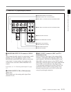
Page 4: Phase (AUDIO)
AUDIO PB ADV.: Shows the phase of the audio
output signal.
OFF: Output in phase with the video output signal.
–1Frame: Output one frame advanced with respect
to the video output signal.
AUDIO INPUT DELAY: Shows the recording
phase of the audio input signal.
OFF: Recorded in phase with the video output
signal.
+1Frame: Recorded one frame delayed with
respect to the video input signal.
AES/EBU & ANALOG OUTPUT: Shows the
phase of the AES/EBU and ANALOG AUDIO
outputs.
REF: Output in phase with reference.
FC: In phase with the FC output.
–90H(HD): 90H (HD) advanced with respect to
reference.
–2H(SD): 2H (SD) advanced with respect to
reference.
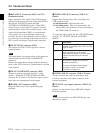
Page 5: Phase (TC)
TC INPUT DELAY: Shows the recording phase of
the input timecode.
OFF: Recorded in phase with the input video
signal.
+1Frame: Recorded one frame delayed with
respect to the input video signal.
LTC OUTPUT: Shows the phase of the output LTC.
LINE: Output in phase with the main line HD SDI
output.
FC: Output in phase with the FC output.
Page 6: Meta Data
META DATE LINE(REC): Shows the three-line
setting for metadata recording on this unit.
META DATE LINE(OUT): Shows the three lines
in which the metadata is included.
DID/SDID: Shows the playback metadata
information.
Note
Make the ACTIVE LINE setting in the SYSTEM
screen. The phase settings and selection of the three
lines for META DATA recording in pages 3, 4, and 5
are made in the PHASE SET menu under the
ALT+OTHERS CHECK menu in the
MAINTENANCE menu.
For details, refer to the Installation Manual.
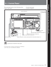
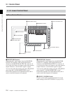
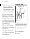
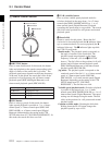
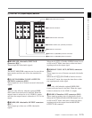
2 REF SYNC (reference signal) indicators
These indicate the signal selected as the reference
signal. If there is no reference signal input to the
selected connector, the STOP button flashes.
EXT SD: Lights when “extern SD” is selected by the
VTR SETUP menu item 006 “EXTERNAL
REFERENCE select”.
EXT HD: Lights when “extern HD” is selected by
the VTR SETUP menu item 006 “EXTERNAL
REFERENCE select”.
INPUT VIDEO: Lights when “INPUT” is selected
by the VTR SETUP menu item 005 “SERVE/AV
REFERENCE select”.
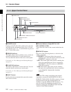
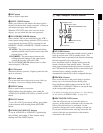
3 PREREAD indicator
Lights up during preread mode.
For more information about PREREAD, see “6-2-3 Preread
Editing” on page 6-15.
4 SERVO indicator
Lights up when the drum servo and capstan servo are
locked.
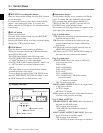
5 REC INHIBIT indicator
The status of this indicator depends on the setting of
the [F2] (REC INH) button in the HOME menu and the
state of the record-protect plug on the cassette.
a) Toggling between lit/flashing settings is possible using
the VTR SETUP menu item 104 “REC INHIBIT LAMP
FLASHING”.
Recording, editing, and selection of assemble and
insert modes are possible only when the indicator is
off.
Setting of the [F2]
(REC INH) button in
the HOME menu
State of the record-
protect plug on the
cassette
REC INHIBIT
indicator
all Recording disabled Lit/flashing
a)
crash REC, video/
CTL, audio/CTL
Recording disabled Lit/flashing
a)
UnlitRecording allowed
Recording allowed Lit
off Recording disabled Lit/flashing
a)
Recording allowed Unlit
a)