


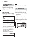

4-3 TC Menu
4-24 Chapter 4 Menu Settings
Chapter 4 Menu Settings
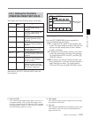
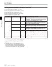
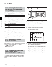
Selecting the time code and the user bits to be recorded
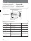
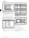
[F7] (TCG MODE) [F6] (REGENE SOURCE) [F9] (DF/NDF) Time code and user bits recorded
prst DF/NDF/
auto
1)
TC/UB enables TUG/UBG values to be recorded. Any time
code can be specified for the time code generator and the user
bits generator. The running mode for the recorded time code
data conforms to that specified by the [F9] button.
regene
2)
int-L TC/UB enables TUG/UBG values to be recorded. The time
code generator and the user bits generator lock to the time
data recorded longitudinally on the tape.
int-V TC/UB enables TUG/UBG values to be recorded. The time
code generator and the user bits generator lock to the time
data recorded in the video signal AUX data area on the tape.
ext-L TC/UB enables TUG/UBG values to be recorded. The time
code generator and the user bits generator lock to the time
data input from the TIME CODE IN connector.
SDI-V TC/UB enables TUG/UBG values to be recorded. TUG/UBG
values are controlled by VITC time data in the video signal
input to the HD SDI INPUT A/B connector.
1) The DF/NDF setting on the [F9] button is applied to the
time code only when “prst” is specified by the [F7]
button; the DF/NDF setting is always applied for the
CTL timer.
2) Specify the signal to be regenerated with the VTR
SETUP menu item 608 “TCG/UBG REGENE MODE”.
Signals not specified by this menu item are automatically
set to Preset mode, regardless of the [F7] button setting.
auto
“regene/int-L” is set in assemble or insert mode and “prst” is
set in other modes.
SDI-L TC/UB enables TUG/UBG values to be recorded. TUG/UBG
values are controlled by LTC time data in the video signal
input to the HD SDI INPUT A/B connector.
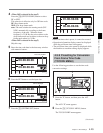
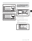
Use the [F6] (REGENE SOURCE), [F7] (TCG
MODE), and [F9] (DF/NDF) buttons in the TC menu
to specify the time code and the user bits to be
recorded. The specifications for the various button
settings are shown in the following table.