


Rev. 1.0, 07/01, page 96 of 372
7.6 Programmer Mode
In programmer mode, a PROM programmer can be used to perform programming/erasing via a
socket adapter, just as a discrete flash memory. Use a PROM programmer that supports the MCU
device type with the on-chip Hitachi 64-kbyte flash memory (F-ZTAT64V5). A 10-MHz input
clock is required. For the conditions for transition to programmer mode, see table 7-1.
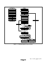
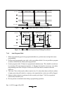
7.6.1 Socket Adapter
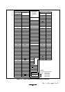
The socket adapter converts the pin allocation of the H8/3694F to that of the discrete flash memory
HN28F101. The address of the on-chip flash memory is H'0000 to H'7FFF. Figure 7-5 shows the
socket-adapter-pin correspondence diagram.
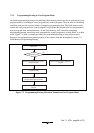
7.6.2 Programmer Mode Commands
The following commands are supported in programmer mode.
•
Memory Read Mode
•
Auto-Program Mode
•
Auto-Erase Mode
•
Status Read Mode
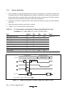
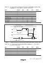
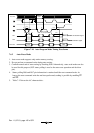
Status polling is used for auto-programming, auto-erasing, and status read modes. In status read
mode, detailed internal information is output after the execution of auto-programming or auto-
erasing. Table 7-7 shows the sequence of each command. In auto-programming mode, 129 cycles
are required since 128 bytes are written at the same time. In memory read mode, the number of
cycles depends on the number of address write cycles (n).
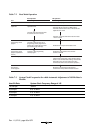
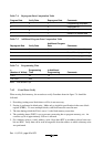
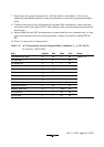
Table 7-7 Command Sequence in Programmer Mode
Number
1st Cycle 2nd Cycle
Command Name of Cycles Mode Address Data Mode Address Data
Memory read 1 + n Write X H'00 Read RA Dout
Auto-program 129 Write X H'40 Write WA Din
Auto-erase 2 Write X H'20 Write X H'20
Status read 2 Write X H'71 Write X H'71
Legend n : the number of address write cycles