


Rev. 1.0, 07/01, page 258 of 372
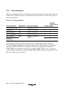
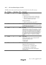
Bit Bit Name Initial Value R/W Description
2
1
0
CH2
CH1
CH0
0
0
0
R/W
R/W
R/W
Channel Select 2 to 0
Select analog input channels.
When SCAN = 0 When SCAN = 1
000: AN0 000: AN0
001: AN1 001: AN0 and AN1
010: AN2 010: AN0 to AN2
011: AN3 011: AN0 to AN3
100: AN4 100: AN4
101: AN5 101: AN4 and AN5
110: AN6 110: AN4 to AN6
111: AN7 111: AN4 to AN7
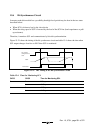
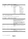
16.3.3 A/D Control Register (ADCR)
The ADCR enables A/D conversion started by an external trigger signal.
Bit Bit Name Initial Value R/W Description
7 TRGE 0 R/W Trigger Enable
A/D conversion is started at the falling edge and
the rising edge of the external trigger signal
(ADTRG) when this bit is set to 1.
The selection between the falling edge and rising
edge of the external trigger pin (ADTRG) comforms
to the WPEG5 bit in the interrupt edge select
register 2 (IEGR2)
6
5
4
3
2
1
—
—
—
—
—
—
1
1
1
1
1
1
—
—
—
—
—
—
Reserved
These bits are always read as 1, and cannot be
modified.
0— 0 R/WReserved
Do not set this bit to 1, though the bit is
readable/writable.