


Rev. 1.0, 07/01, page 78 of 372
6.2.4 Subactive Mode
The operating frequency of the subactive mode is selected from ø
W
/2, ø
W
/4, and ø
W
/8 by the SA1
and SA0 bits in SYSCR2. The operating frequency changes to the set frequency after SLEEP
instruction execution. When the SLEEP instruction is executed in the subactive mode, a transition
to the sleep mode, subsleep mode, standby mode, active mode, or subactive mode is made,
depending on the combination of SYSCR1 and SYSCR2. When the RES pin goes low, the system
clock pulse generator starts. Since system clock signals are supplied to the entire chip as soon as
the system clock pulse generator starts functioning, the RES pin must be kept low until the pulse
generator output stabilizes. After the pulse generator output has stabilized, the CPU starts reset
exception handling if the RES pin is driven high.
6.3 Operating Frequency in the Active Mode
Operation in the active mode is clocked at the frequency designated by the MA2, MA1, and MA0
bits in SYSCR2. The operating frequency changes to the set frequency after SLEEP instruction
execution.
6.4 Direct Transition
The CPU can execute programs in two modes: active and subactive mode. A direct transition is a
transition between these two modes without stopping program execution. A direct transition can
be made by executing a SLEEP instruction while the DTON bit in SYSCR2 is set to 1. The direct
transition also enables operating frequency modification in the active or subactive mode. After the
mode transition, direct transition interrupt exception handling starts.
If the direct transition interrupt is disabled in interrupt enable register 1, a transition is made
instead to the sleep or subsleep mode. Note that if a direct transition is attempted while the I bit in
CCR is set to 1, the sleep or subsleep mode will be entered, and the resulting mode cannot be
cleared by means of an interrupt.
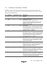
6.4.1 Direct Transition from the Active Mode to the Subactive Mode
The time from the start of SLEEP instruction execution to the end of interrupt exception handling
(the direct transition time) is calculated by equation (1).
Direct transition time = {(number of SLEEP instruction execution states) + (number of internal
processing states)}× (tcyc before transition) + (number of interrupt exception handling states) ×
(tsubcyc after transition) (1)
Example
Direct transition time = (2 + 1) × tosc + 14 × 8tw = 3tosc + 112tw
(when the CPU operating clock of ø
osc
→ ø
w
/8 is selected)