


Rev. 1.0, 07/01, page 269 of 372
V
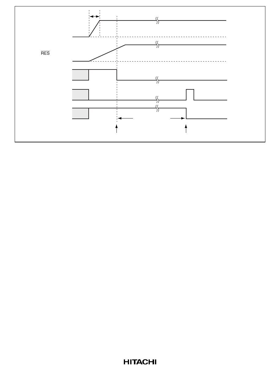
CC
V
SS
V
SS
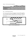
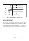
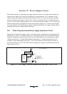
OVF
PSS-reset
signal
Internal reset
signal
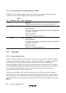
PSS counter starts
Reset released
131,072 cycles
t
PWON
Figure 17-2 Operational Timing of the Power-on Reset Circuit
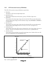
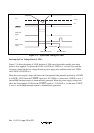
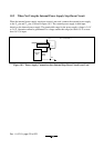
17.3.2 Low-Voltage Detection Circuit
Reset by Low Voltage Detect (LVDR):
Figure 17-3 shows the timing of the LVDR function. LVDR enters the module-standby state when
power is first supplied. To operate the LVDR, set LVDE in LVDCR to 1, wait for 10 µs until the
reference voltage and the low-voltage-detection power supply have stabilized, then set LVDRE in
LVDCR to 1.
When the power-supply voltage falls below the Vreset potential (typ. = 2.2 V), LVDR clears the
LVDRES signal to 0, and resets the prescaler S. The reset state remains in place until a power-on
reset is generated. When the power-supply voltage rises above the Vreset potential, PSS starts
counting. It counts 131,072 clock (φ) cycles, and then releases the internal reset signal.