


Rev. 1.0, 07/01, page 55 of 372
3.5 Usage Notes
3.5.1 Interrupts after Reset
If an interrupt is accepted after a reset and before the stack pointer (SP) is initialized, the PC and
CCR will not be saved correctly, leading to a program crash. To prevent this, all interrupt requests,
including NMI, are disabled immediately after a reset. Since the first instruction of a program is
always executed immediately after the reset state ends, make sure that this instruction initializes
the stack pointer (example: MOV.W #xx: 16, SP).
3.5.2 Notes on Stack Area Use
When word data is accessed, the least significant bit of the address is regarded as 0. Access to the
stack always takes place in word size, so the stack pointer (SP: R7) should never indicate an odd
address. Use PUSH Rn (MOV.W Rn, @–SP) or POP Rn (MOV.W @SP+, Rn) to save or restore
register values.
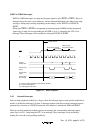
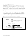
3.5.3 Notes on Rewriting Port Mode Registers
When a port mode register is rewritten to switch the functions of external interrupt pins, IRQ3 to
IRQ0, and WKP5 to WKP0, the interrupt request flag may be set to 1.
When switching a pin function, mask the interrupt before setting the bit in the port mode register.
After accessing the port mode register, execute at least one instruction (e.g., NOP), then clear the
interrupt request flag from 1 to 0.
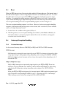
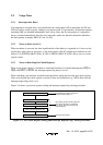
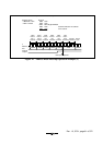
Figure 3-4 shows a port mode register setting and interrupt request flag clearing procedure.
CCR I bit 1
Set port mode register bit
Execute NOP instruction
Interrupts masked. (Another possibility
is to disable the relevant interrupt in
interrupt enable register 1.)
After setting the port mode register bit,
first execute at least one instruction
(e.g., NOP), then clear the interrupt
request flag to 0.
Interrupt mask cleared
Clear interrupt request flag to 0
←
CCR I bit 0
←
Figure 3-4 Port Mode Register Setting and Interrupt Request Flag Clearing Procedure