


Rev. 1.0, 07/01, page 64 of 372
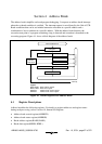
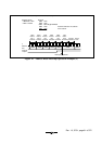
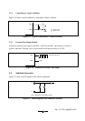
LPM
Note : LPM: Low-power mode (standby mode, subactive mode, or subsleep mode)
2
1
OSC
OSC
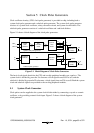
Figure 5-2 Block Diagram of the System Clock Generator
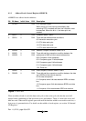
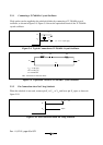
5.1.1 Connecting a Crystal Oscillator
Figure 5-3 shows a typical method of connecting a crystal oscillator. An AT-cut parallel-
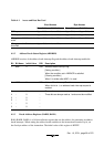
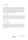
resonance crystal resonator should be used. Figure 5-4 shows the equivalent circuit of a crystal
oscillator. An oscillator having the characteristics given in table 5-1 should be used.
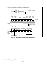
1
2
C
1
C
2
OSC
OSC
C = C = 12 pF ±20%
12
Figure 5-3 Typical Connection to Crystal Oscillator
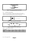
C
S
C
0
R
S
OSC
1
OSC
2
L
S
Figure 5-4 Equivalent Circuit of Crystal Oscillator
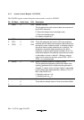
Table 5-1 Crystal Oscillator Parameters
Frequency(MHz) 2481016
R
S
(max) 500 Ω 120 Ω 80 Ω 60 Ω 50 Ω
C
0
(max) 7 pF 7 pF 7 pF 7 pF 7 pF