


Rev. 1.0, 07/01, page 134 of 372
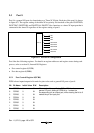
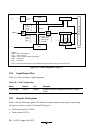
10.3.2 Timer Counter A (TCA)
TCA is an 8-bit readable up-counter, which is incremented by internal clock input. The clock
source for input to this counter is selected by bits TMA3 to TMA0 in TMA. TCA values can be
read by the CPU in active mode, but cannot be read in subactive mode. When TCA overflows, the
IRRTA bit in interrupt request register 1 (IRR1) is set to 1. TCA is cleared by setting bits TMA3
and TMA2 of TMA to 11. TCA is initialized to H'00.
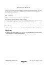
10.4 Operation
10.4.1 Interval Timer Operation
When bit TMA3 in TMA is cleared to 0, timer A functions as an 8-bit interval timer.
Upon reset, TCA is cleared to H'00 and bit TMA3 is cleared to 0, so up-counting of timer A
resume immediately as an interval timer. The clock input to timer A is selected by bits TMA2 to
TMA0 in TMA; any of eight internal clock signals output by prescaler S can be selected.
After the count value in TCA reaches H'FF, the next clock signal input causes timer A to
overflow, setting bit IRRTA to 1 in interrupt Flag Register 1 (IRR1). If IENTA = 1 in interrupt
enable register 1 (IENR1), a CPU interrupt is requested. At overflow, TCA returns to H'00 and
starts counting up again. In this mode timer A functions as an interval timer that generates an
overflow output at intervals of 256 input clock pulses.
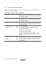
10.4.2 Clock Time Base Operation
When bit TMA3 in TMA is set to 1, timer A functions as a clock-timer base by counting clock
signals output by prescaler W. When a clock signal is input after the TCA counter value has
become H'FF, timer A overflows and IRRTA in IRR1 is set to 1. At that time, an interrupt request
is generated to the CPU if IENTA in the interrupt enable register 1 (IENR1) is 1. The overflow
period of timer A is set by bits TMA1 and TMA0 in TMA. A choice of four periods are available.
In clock time base operation (TMA3 = 1), setting bit TMA2 to 1 clears both TCA and prescaler W
to H'00.
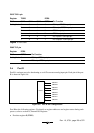
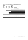
10.4.3 Clock Output
Setting bit TMOW in port mode register 1 (PMR1) to 1 causes a clock signal to be output at pin
TMOW. Eight different clock output signals can be selected by means of bits TMA7 to TMA5 in
TMA. The system clock divided by 32, 16, 8, or 4 can be output in active mode and sleep mode. A
32.768 kHz signal divided by 32, 16, 8, or 4 can be output in active mode, sleep mode, and
subactive mode.