


Rev. 1.0, 07/01, page 333 of 372
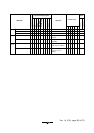
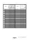
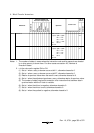
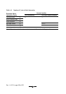
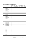
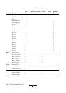
8. Block Transfer Instructions
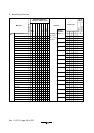
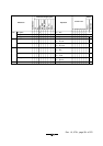
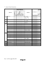
Mnemonic
Operand Size
Addressing Mode and
Instruction Length (bytes)
No. of
States
*1
Condition Code
IHNZVC
#xx
Rn
@ERn
@(d, ERn)
@–ERn/@ERn+
@aa
@(d, PC)
@@aa
—
EEPMOV. B
EEPMOV. W
Operation
if R4L ≠ 0 then
repeat @R5 → @R6
R5+1 → R5
R6+1 → R6
R4L–1 → R4L
until R4L=0
else next
if R4 ≠ 0 then
repeat @R5 → @R6
R5+1 → R5
R6+1 → R6
R4–1 → R4
until R4=0
else next
—
—
4
4
—
—
8+
4n
*2
Normal
Advanced
—
—
—
—
—
—
—
—
—
—8+
4n
*2
EEPMOV
Notes: 1. The number of states in cases where the instruction code and its operands are located
in on-chip memory is shown here. For other cases see section A.3, Number of
Execution States.
2. n is the value set in register R4L or R4.
(1) Set to 1 when a carry or borrow occurs at bit 11; otherwise cleared to 0.
(2) Set to 1 when a carry or borrow occurs at bit 27; otherwise cleared to 0.
(3) Retains its previous value when the result is zero; otherwise cleared to 0.
(4) Set to 1 when the adjustment produces a carry; otherwise retains its previous value.
(5) The number of states required for execution of an instruction that transfers data in
synchronization with the E clock is variable.
(6) Set to 1 when the divisor is negative; otherwise cleared to 0.
(7) Set to 1 when the divisor is zero; otherwise cleared to 0.
(8) Set to 1 when the quotient is negative; otherwise cleared to 0.