


Rev. 1.0, 07/01, page 177 of 372
Section 13 Watchdog Timer
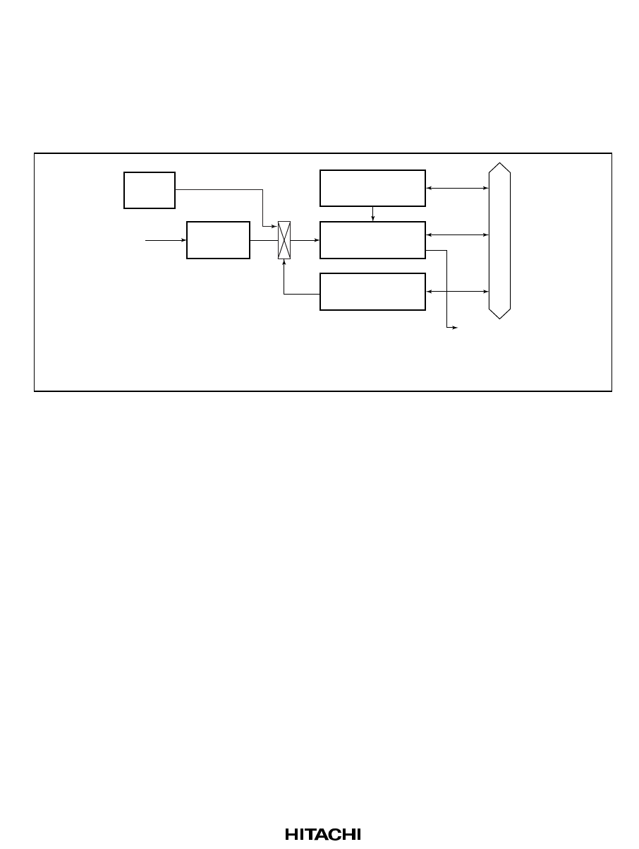
The watchdog timer(WDT) is an 8-bit timer that can generate an internal reset signal for this LSI
if a system crash prevents the CPU from writing to the timer counter, thus allowing it to overflow.
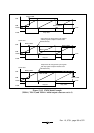
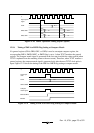
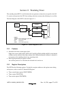
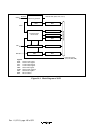
The block diagram of the WDT is shown in figure 13-1.
ø
Internal reset
signal
PSS TCWD
TMWD
TCSRWD
Internal data bus
Legend:
TCSRWD: Timer control/status register WD
TCWD: Timer counter WD
PSS: Prescaler S
TMWD: Timer mode register WD
Internal
oscillator
CLK
Figure 13-1 Block Diagram of WDT
13.1 Features
•
Selectable from nine counter input clocks.
Eight clock sources (
φ
/64,
φ
/128,
φ
/256,
φ
/512,
φ
/1024,
φ
/2048,
φ
/4096,
φ
/8192) or the internal
oscillator can be selected as the timer-counter clock. When the internal oscillator is selected, it
can operate as the watchdog timer in any operating mode.
•
Reset signal generated on counter overflow
An overflow period of 1 to 256 times the selected clock can be set.
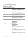
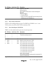
13.2 Register Descriptions
The WDT has the following registers. For details on register addresses and register states during
each process, refer to section 19, Internal I/O Register.
•
Timer control/status register WD(TCSRWD)
•
Timer counter WD(TCWD)
•
Timer mode register WD(TMWD)
WDT0110A0000_000020010700