


Rev. 1.0, 07/01, page 147 of 372
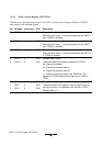
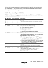
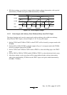
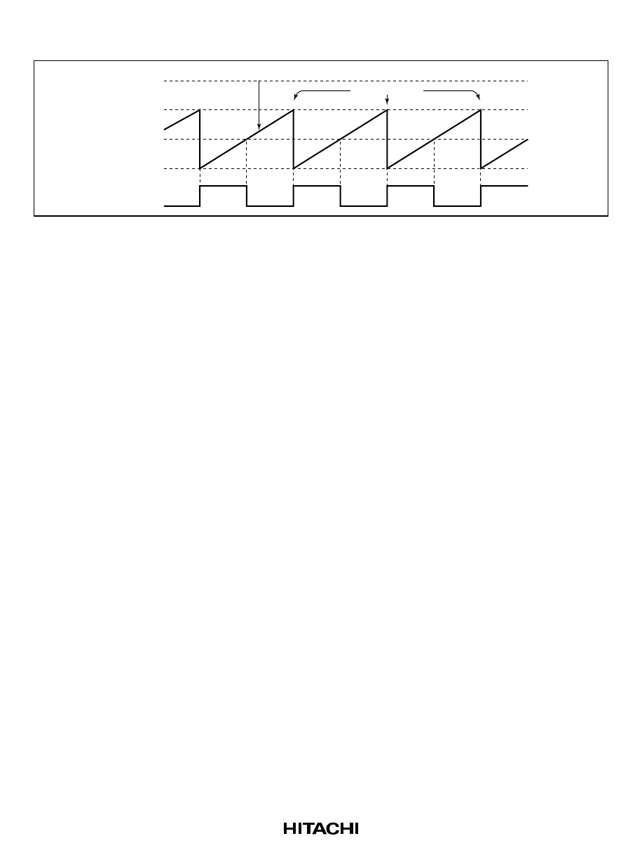
4. With these settings, a waveform is output without further software intervention, with a period
determined by TCORA and a pulse width determined by TCORB.
Counter cleared
TCNTV
H'FF
TCORA
TCORB
H'00
TMOV
Figure 11-9 Pulse Output Example
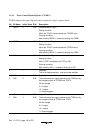
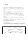
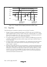
11.5.2 Pulse Output with Arbitrary Pulse Width and Delay from TRGV Input
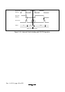
The trigger function can be used to output a pulse with an arbitrary pulse width at an arbitrary
delay from the TRGV input, as shown in figure 11-10. To set up this output:
1. Set bits CCLR1 and CCLR0 in TCRV0 so that TCNTV will be cleared by compare match with
TCORB.
2. Set bits OS3 to OS0 in TCSRV so that the output will go to 1 at compare match with TCORA
and to 0 at compare match with TCORB.
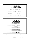
3. Set bits TVEG1 and TVEG0 in TCRV1 and set TRGE to select the falling edge of the TRGV
input.
4. Set bits CKS2 to CKS0 in TCRV0 and bit ICKS0 in TCRV1 to select the desired clock source.
5. After these settings, a pulse waveform will be output without further software intervention,
with a delay determined by TCORA from the TRGV input, and a pulse width determined by
(TCORB – TCORA).