


Rev. 1.0, 07/01, page 234 of 372
15.4 Operation
The I
2
C bus interface can communicate either in I
2
C bus mode or clocked synchronous serial mode
by setting FS in SAR.
15.4.1 I
2
C Bus Format
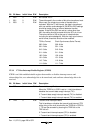
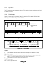
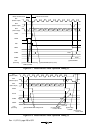
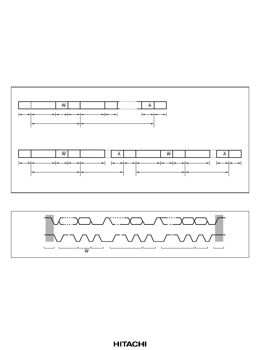
Figure 15-3 shows the I
2
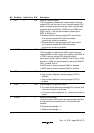
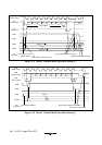
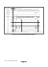
C bus formats. Figure 15-4 shows the I
2
C bus timing. The first frame
following a start condition always consists of 8 bits.
S SLA R/ A DATA A A/ P
1111
n7
1 m
(a) I
2
C bus format (FS = 0)
(b) I
2
C bus format (Start condition retransmission, FS = 0)
n: Transfer bit count
(n = 1 to 8)
m: Transfer frame count
(m ≥ 1)
S SLA R/ A DATA
111
n17
1 m1
S SLA R/ A DATA A/ P
111
n27
1 m2
111
A/
n1 and n2: Transfer bit count (n1 and n2 = 1 to 8)
m1 and m2: Transfer frame count (m1 and m2 ≥ 1)
11
Figure 15-3 I
2
C Bus Formats
SDA
SCL
S
1-7
SLA
8
R/
9
A
1-7
DATA
89 1-7 89
A DATA PA
Figure 15-4 I
2
C Bus Timing
Legend
S: Start condition. The master device drives SDA from high to low while SCL is high.
SLA: Slave address
R/W: Indicates the direction of data transfer: from the slave device to the master device when
R/W is 1, or from the master device to the slave device when R/W is 0.
A: Acknowledge. The receive device drives SDA to low.
DATA:Transfer data