


Rev. 1.0, 07/01, page 219 of 372
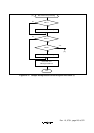
14.8.4 Receive Data Sampling Timing and Reception Margin in Asynchronous Mode
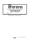
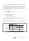
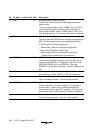
In asynchronous mode, the SCI operates on a basic clock with a frequency of 16 times the transfer
rate. In reception, the SCI samples the falling edge of the start bit using the basic clock, and
performs internal synchronization. Receive data is latched internally at the rising edge of the 8th
pulse of the basic clock as shown in figure 14-19. Thus, the reception margin in asynchronous
mode is given by formula (1) below.
M = (0.5 – ) – – (L – 0.5) F × 100(%)
1
2N
D – 0.5
N
... Formula (1)
Legend N : Ratio of bit rate to clock (N = 16)
D : Clock duty (D = 0.5 to 1.0)
L : Frame length (L = 9 to 12)
F : Absolute value of clock rate deviation
Assuming values of F (absolute value of clock rate deviation) = 0 and D (clock duty) = 0.5 in
formula (1), the reception margin can be given by the formula.
M = {0.5 – 1/(2 × 16)} × 100 [%] = 46.875%
However, this is only the computed value, and a margin of 20% to 30% should be allowed for in
system design.
Internal basic
clock
16 clocks
8 clocks
Receive data
(RxD)
Synchronization
sampling timing
Start bit D0 D1
Data sampling
timing
15 0 7 15 007
Figure 14-19 Receive Data Sampling Timing in Asynchronous Mode