


Rev. 1.0, 07/01, page 197 of 372
14.4.3 Data Transmission
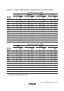
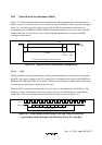
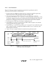
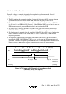
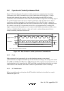
Figure 14-5 shows an example of operation for transmission in asynchronous mode. In
transmission, the SCI operates as described below.
1. The SCI monitors the TDRE flag in SSR. If the flag is cleared to 0, the SCI recognizes that
data has been written to TDR, and transfers the data from TDR to TSR.
2. After transferring data from TDR to TSR, the SCI sets the TDRE flag to 1 and starts
transmission. If the TIE bit is set to 1 at this time, a transmit data empty interrupt request (TXI)
is generated. Continuous transmission is possible because the TXI interrupt routine writes next
transmit data to TDR before transmission of the current transmit data has been completed.
3. The SCI checks the TDRE flag at the timing for sending the stop bit.
4. If the TDRE flag is 0, the data is transferred from TDR to TSR, the stop bit is sent, and then
serial transmission of the next frame is started.
5. If the TDRE flag is 1, the TEND flag in SSR is set to 1, the stop bit is sent, and then the “mark
state” is entered, in which 1 is output. If the TEIE bit in SCR3 is set to 1 at this time, a TEI
interrupt request is generated.
6.
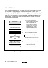
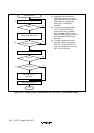
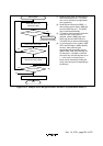
Figure 14-6 shows a sample flowchart for transmission in asynchronous mode.
1 frame
Start
bit
Start
bit
Transmit
data
Transmit
data
Parity
bit
Stop
bit
Parity
bit
Stop
bit
Mark
state
1 frame
01 D0 D1 D7 0/1 1 1 10 D0 D1 D7 0/1
Serial
data
TDRE
TEND
LSI
operation
TXI interrupt
request
generated
TDRE flag
cleared to 0
User
processing
Data written
to TDR
TXI interrupt request generated TEI interrupt request
generated
Figure 14-5 Example of SCI Transmission in Asynchronous Mode
(8-Bit Data, Parity, One Stop Bit)