


Rev. 1.0, 07/01, page 59 of 372
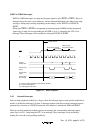
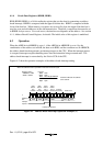
Table 4-1 Access and Data Bus Used
Word Access Byte Access
Even Address Odd Address Even Address Odd Address
ROM space Upper 8 bits Lower 8 bits Upper 8 bits Upper 8 bits
RAM space Upper 8 bits Lower 8 bits Upper 8 bits Upper 8 bits
I/O register with 8-bit data bus
width
Upper 8 bits Upper 8 bits Upper 8 bits Upper 8 bits
I/O register with 16-bit data
bus width
Upper 8 bits Lower 8 bits — —
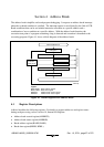
4.1.2
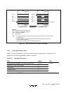
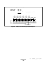
Address Break Status Register(ABRKSR)
ABRKSR consists of the address break interrupt flag and the address break interrupt enable bit.
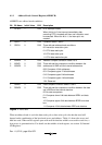
Bit Bit Name Initial Value R/W Description
7 ABIF 0 R/W Address Break Interrupt Flag
[Setting condition]
When the condition set in ABRKCR is satisfied
[Clearing condition]
When 0 is written after ABIF=1 is read
6 ABIE 0 R/W Address Break Interrupt Enable
When this bit is 1, an address break interrupt request is
enabled.
5
4
3
2
1
0
−
−
−
−
−
−
0
0
0
0
0
0
−
−
−
−
−
−
Reserved
These bits are always read as 1 and cannot be modified.
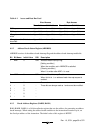
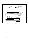
4.1.3 Break Address Registers (BARH, BARL)
BAR (BARH, BARL) is a 16-bit read/write register that sets the address for generating an address
break interrupt. When setting the address break condition to the instruction execution cycle, set
the first byte address of the instruction. The initial value of this register is H'FFFF.